
Electric direct-acting actuator and electric brake apparatus

An electric, actuator technology, applied in the direction of transmission, friction transmission, brake type, etc., can solve the problem of difficult to stably capture the timing and instability of sudden changes in differential value

Inactive Publication Date: 2014-07-30
NTN CORP
View PDF7 Cites 26 Cited by
  • Summary
  • Abstract
  • Description
  • Claims
  • Application Information

AI Technical Summary

Problems solved by technology

[0011] However, since the differential value of the output of the load sensor is actually an unstable value near the load being 0, it is actually difficult to stably capture the timing of sudden changes in the differential value.

Method used


Image

  • Electric direct-acting actuator and electric brake apparatus
  • Electric direct-acting actuator and electric brake apparatus
  • Electric direct-acting actuator and electric brake apparatus

Examples


Embodiment Construction

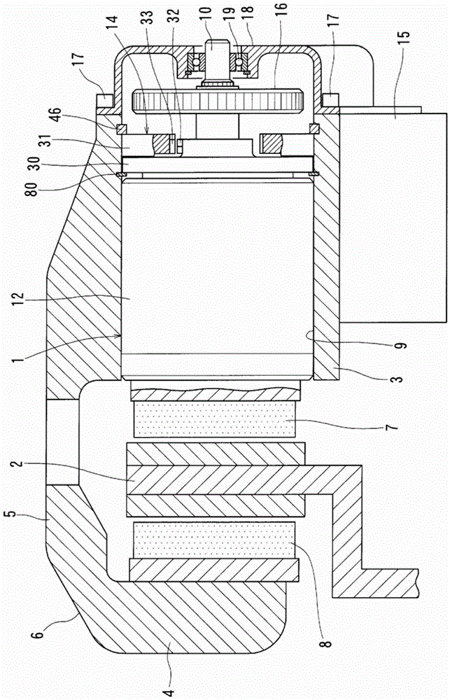
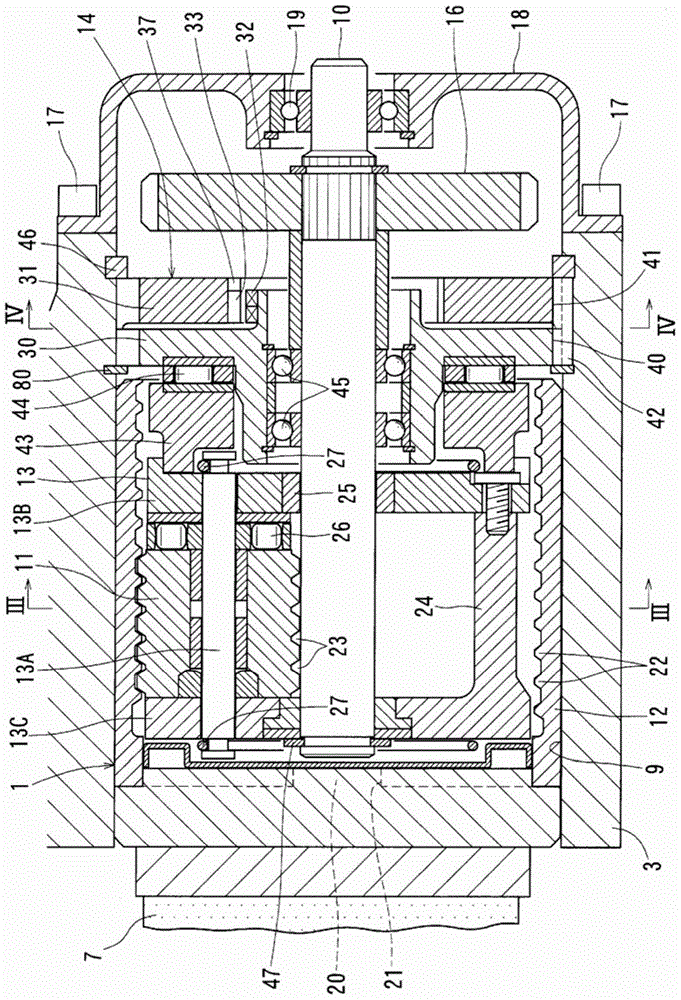
[0039] exist figure 1 An electric braking device for a vehicle using the electric linear actuator 1 according to the embodiment of the present invention. This electric braking device has a brake caliper body 6 in the shape of connecting opposing plates 3, 4 by a bridge 5, and a pair of left and right friction pads 7, 8, wherein the opposing plates 3, 4 are spaced between them with the wheel. The integrally rotating brake discs 2 are arranged facing each other. Furthermore, the electric linear actuator 1 is assembled into the housing hole 9 opened on the surface of the facing piece 3 facing the brake disc 2 .

[0040] The friction pads 7, 8 are respectively provided between the opposing plates 3, 4 and the brake disc 2, and are supported so as to be able to be aligned with a fixing member (not shown) fixed to a steering knuckle (not shown) supporting the wheel. Axial movement of the disc 2. In addition, the caliper body 6 is also supported by the fixture so as to be slidable...


PUM


Abstract

Provided is an electric direct-acting actuator for making it possible to set the clearance for when an electric brake apparatus runs a normal brake operation. The present invention is equipped with a load sensor (14) for detecting the magnitude of the load pressing against a brake disk (2) with a friction pad (7); a temperature sensor (37) for correcting for the effects of temperature on the load sensor (14); and an electronic control device (50). The electronic control device (50) calculates, on the basis of the magnitude of the load detected by the load sensor (14), the rotation angle ([theta]) of an electric motor (15) from the position of the electric motor (15) corresponding to the magnitude of the load to the position of the electric motor (15) where clearance reaches a predetermined magnitude, and causes the electric motor (15) to rotate using the rotation angle ([theta]) as a target value.

Description

technical field [0001] The present invention relates to an electric linear actuator that converts the rotation of a rotary shaft driven by an electric motor into linear motion of a linear motion member, presses an object with the linear motion member, and an electric linear motion actuator using the electric linear motion actuator. Electric braking device. Background technique [0002] As a brake device for a vehicle, a hydraulic brake device that drives a friction pad with a hydraulic cylinder to press the brake disc is used, but in recent years, with the introduction of brake control such as ABS (anti-lock brake system), it has not been used. The electric braking device of the hydraulic circuit has attracted attention. [0003] The electric brake device uses an electric linear actuator that converts the rotation of a rotary shaft driven by an electric motor into the linear motion of a linear motion member, and presses the brake disc with a brake pad driven by this electri...

Claims


Application Information

Patent Timeline
Patent Type & Authority Applications(China)
IPC IPC(8): F16D65/18F16D55/00F16D65/14F16D65/62F16D65/68F16H19/02
CPCF16H25/2252F16D55/00F16D65/14F16D65/18F16D65/62F16D65/68F16D2066/003F16D2066/005F16D2121/24F16D2125/36F16D2125/40F16D2125/48F16H25/2021F16H25/2204
Inventor 山崎达也增田唯村松诚江口雅章竿山祐辉
Owner NTN CORP
Learn More