Laser tracker with position-sensitive detectors for searching for a target

A laser tracker, target position technology, applied in the field of target search, can solve problems such as unreliable search, time-consuming searching and targeting of targets, and inability to fuzzy matching

Active Publication Date: 2014-07-30
LEICA GEOSYSTEMS AG
View PDF5 Cites 22 Cited by
  • Summary
  • Abstract
  • Description
  • Claims
  • Application Information

AI Technical Summary

Problems solved by technology

Therefore, this approach method has the disadvantages that searching and aiming at the target is a time-consuming operation (because it is cyclic), and the search is not reliable and cannot be fuzzy matched, especially if the target moves relative to the sensor
In general, therefore, a great disadvantage of this aiming system also leads to the fact that only stationary targets are aimed at with relatively long time consumption, and direct aiming at moving targets is impossible

Method used


Image

  • Laser tracker with position-sensitive detectors for searching for a target
  • Laser tracker with position-sensitive detectors for searching for a target
  • Laser tracker with position-sensitive detectors for searching for a target

Examples


Embodiment Construction

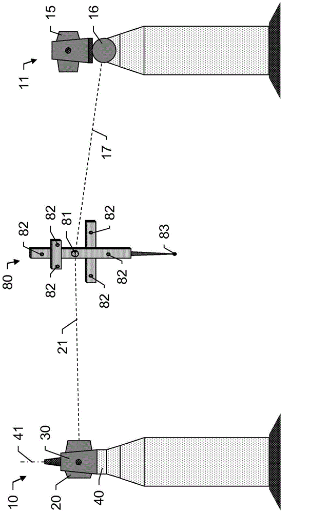
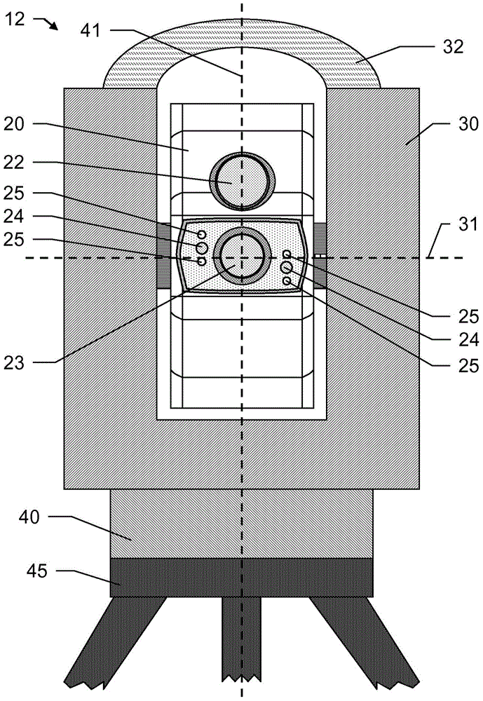
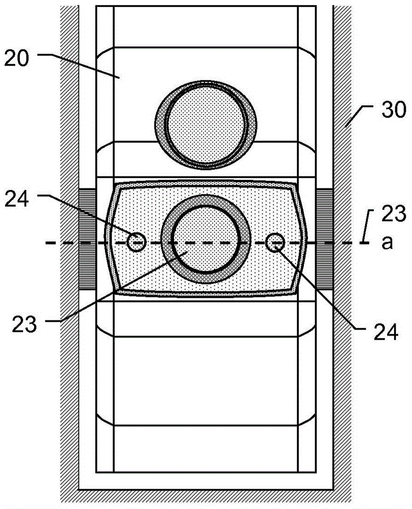
[0055] figure 1 Two embodiments of laser trackers 10 , 11 and measurement aids 80 (eg tactile measurement devices) according to the invention are shown. The first laser tracker 10 has a base 40 and a support 30 , wherein the support 30 is arranged such that it can pivot or rotate relative to the base 40 about a pivot axis 41 defined by the base 40 . In addition, the aiming unit 20 is arranged on the support 30 such that the aiming unit 20 can pivot relative to the support 30 about a tilt axis (rotation axis). Through the alignment function thus provided by the aiming unit 20 about two axes, it is possible to flexibly align the laser beam 21 emitted by this unit 20 and thus aim at the target. In this case, the pivot axis 41 and the tilt axis are arranged substantially orthogonally to each other, ie a slight offset from a position exactly orthogonal to the axis can eg be predetermined and stored in the system in order to compensate for measurement errors thus occurring.

[005...


PUM


Abstract

The invention relates to a laser tracker (12) for continuously pursuing a reflective target and for determining the position of the target, comprising a base (40) which defines a vertical axis (41), a beam guiding unit for emitting a measurement beam, the beam guiding unit being pivotable by motor relative to the base (40) about the vertical axis (41) and an inclination axis (31), and a measurement axis (57) being defined by an emission direction of the measurement beam. The invention further comprises a precision distance measurement unit for precisely determining the distance to the target, an angle measurement function for determining alignment of the beam guiding unit relative to the base (40) and a target search unit. The target search unit has illumination means (25) for illuminating the target, a first camera (24) with a first position-sensitive detector, a first image being acquirable with the first camera (24) and, in the first image, at least one part of the illumination beam reflected on the target being determinable as a first target position, and a control and evaluation unit. The target search unit also has a second camera (24) with a second position-sensitive detector, a second image being acquirable with the second camera (24) and, in the second image, at least one part of the illumination beam reflected on the target being determinable as a second target position and the second camera (24) being arranged with a camera positioning that is known or fixed in relation to the first camera (24) in such a manner that the fields of vision of the first and second cameras (24) at least partially overlap. When the search function is operated, the target is located in relation to the first and second target positions.

Description

technical field [0001] The invention relates to a coordinate measuring device, in particular to a laser tracker for continuously tracking a reflective target according to the preamble of claim 1 and for determining the distance to the target, and a method of finding a target according to claim 15 . Background technique [0002] A surveying device implemented to continuously track a point of interest and determine the coordinate position of this point can be summarized under the term "laser tracker", especially when combined with industrial surveying. In this case, the target point may be represented by a retro-reflective unit (for example a cube prism) which is aimed at with a measuring beam (in particular a laser beam) of the measuring device. The laser beam is reflected parallel back to the measuring device, wherein the reflected beam is acquired using the acquisition unit of the device. In this case, for example, the emission or reception direction of the light beam is d...

Claims


Application Information

Patent Timeline
IPC IPC(8): G01S17/66G06T7/00
CPCG01S17/66G01S13/66G06T7/00G01B11/14
Inventor A·马肯多夫
Owner LEICA GEOSYSTEMS AG
Why Eureka
Try Eureka