Supercharge Your Innovation With Domain-Expert AI Agents!

LED superconductive board vacuum water injection equipment

A technology for water injection equipment and superconducting plates, which is applied in lighting and heating equipment, semiconductor devices of light-emitting elements, cooling/heating devices for lighting devices, etc., can solve the problems of low water injection efficiency, high labor intensity, and low production efficiency, etc. Achieve the effect of ensuring practicability and production, reducing labor intensity and improving production efficiency

Inactive Publication Date: 2014-08-06
郑华卫
View PDF5 Cites 0 Cited by
  • Summary
  • Abstract
  • Description
  • Claims
  • Application Information

AI Technical Summary

Problems solved by technology

At present, the existing LED module has a heat dissipation plate (equal to the LED superconducting plate of the present application), the heat dissipation performance of the heat dissipation plate directly affects the stability of the entire LED module; the existing heat dissipation plate generally injects Pure water is used for heat dissipation. At present, there are at least the following defects in some of these water injection equipments: when water is injected, it is inconvenient to control the clamping of the cooling plate by the water injection equipment; secondly, the production efficiency of the entire equipment is low; , the water injection equipment is inconvenient to close the nozzle of the cooling plate and the sealing efficiency is low, the quality is poor and the labor intensity is high;
[0004] The above-mentioned scheme has improved the existing technology to a certain extent, but the scheme also has at least the following defects: low production efficiency, high labor intensity, low water injection efficiency and poor product quality, poor practicability of the whole scheme, unable to meet production requirements and other technologies question

Method used


Image

  • LED superconductive board vacuum water injection equipment
  • LED superconductive board vacuum water injection equipment
  • LED superconductive board vacuum water injection equipment

Examples


Embodiment Construction

[0024] The present invention will be described in further detail below in conjunction with the accompanying drawings and specific embodiments.

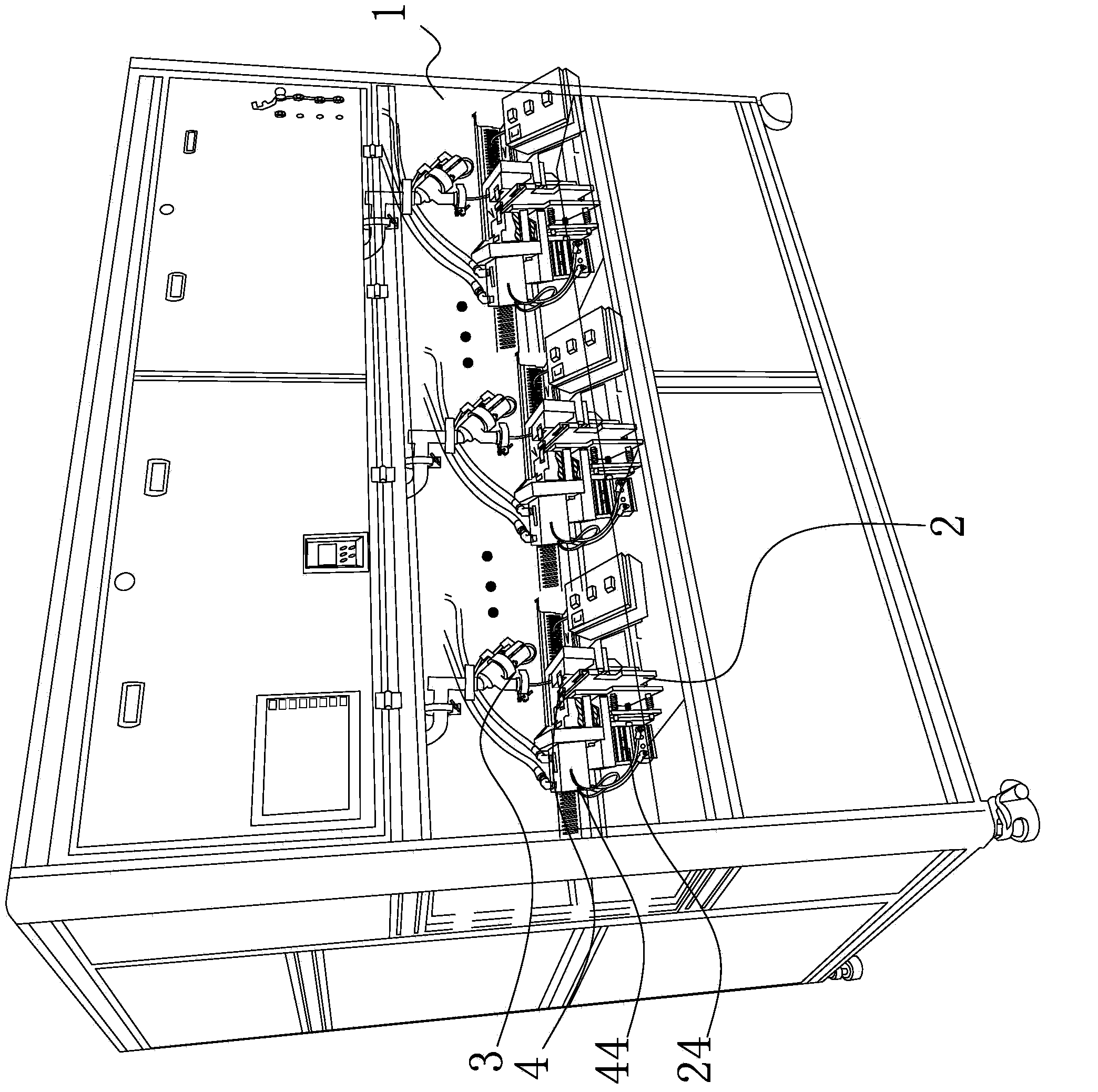
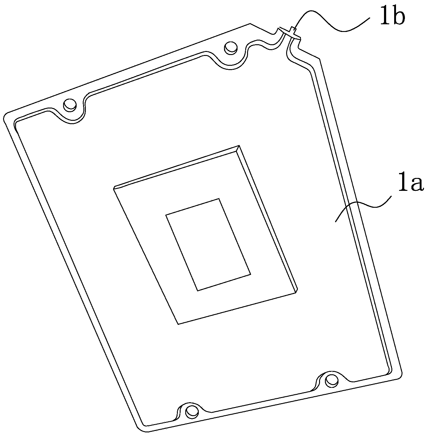
[0025] Such as Figure 1-5 As shown, the LED superconducting plate vacuum water injection equipment includes a workbench 1, on which at least one clamping mechanism 2 for clamping the LED superconducting plate 1a is arranged, above each clamping mechanism 2 A vacuum water injection mechanism 3 is respectively provided, and above each clamping mechanism 2, a vacuum water injection mechanism 3 is provided to connect the LED superconducting plate 1a when the inner cavity of the LED superconducting plate 1a is filled with water delivered by the vacuum water injection mechanism 3. The sprue 1b that the cavity communicates with is closed by the sprue closing mechanism 4 . This embodiment can be a structure with multiple stations, and the actual stations are set according to actual production requirements.

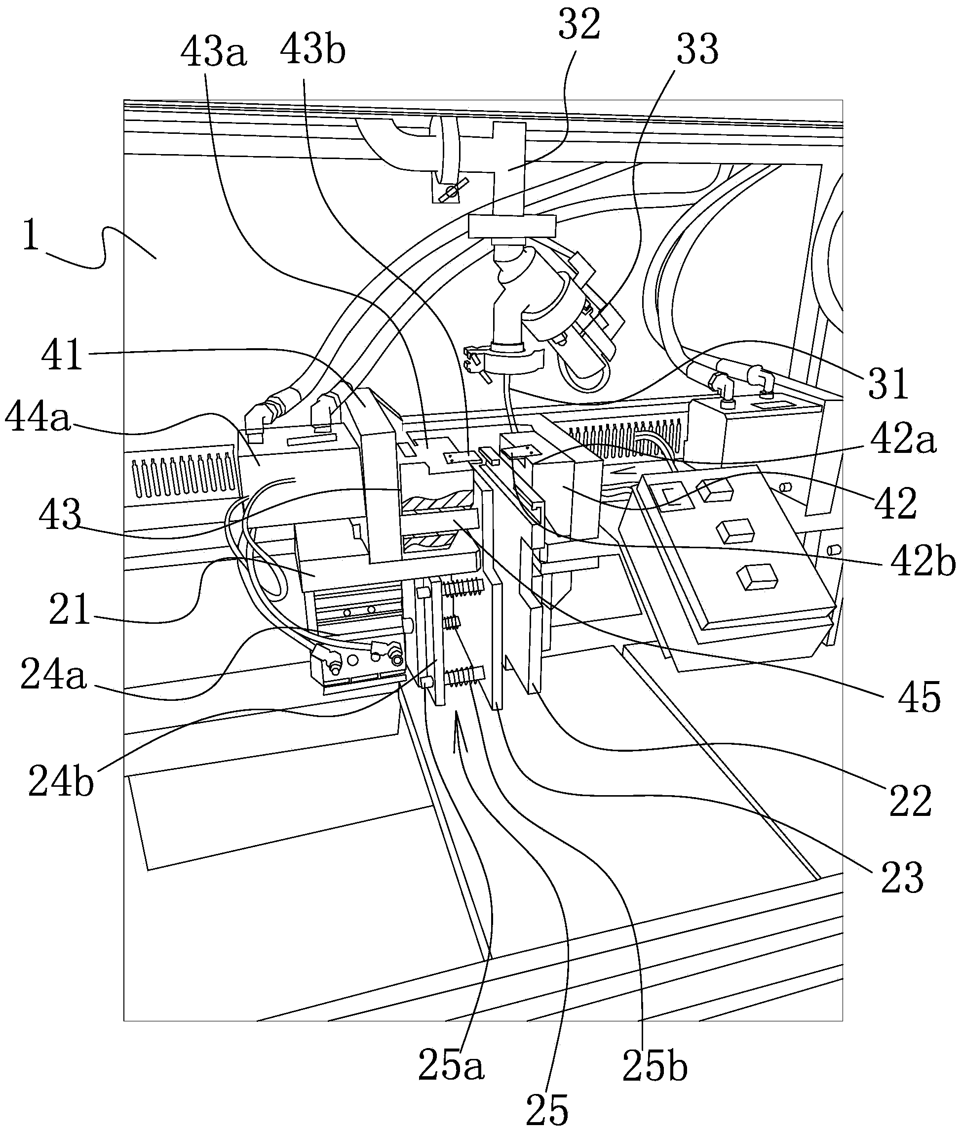
[0026] Such as Figure 1-2 As ...


PUM


Abstract

The invention belongs to the technical field of water injection equipment, and particularly relates to LED superconductive board vacuum water injection equipment. The technical problem that the production efficiency in the prior art is low is solved. The LED superconductive board vacuum water injection equipment comprises a workbench which is provided with at least one clamping mechanism used for clamping an LED superconductive board, a vacuum water injection mechanism is arranged above each clamping mechanism, and an injection opening sealing mechanism which enables an injection opening communicated with an inner cavity of the LED superconductive board to be sealed after the inner cavity of the LED superconductive board is filled with water conveyed by the corresponding vacuum water injection mechanism is arranged above each clamping mechanism. The LED superconductive board vacuum water injection equipment has the advantages that the production efficiency is high, and the practicability is high.

Description

technical field [0001] The invention belongs to the technical field of water injection equipment, and in particular relates to vacuum water injection equipment for LED superconducting plates. Background technique [0002] LED module is a widely used product in LED products. There are also great differences in structure and electronics. The simple one is to use a circuit board and shell equipped with LEDs to form an LED module. The more complicated one is Coupled with some control, constant current source and related heat dissipation, the LED life and luminous intensity are better. At present, the existing LED module has a heat dissipation plate (equal to the LED superconducting plate of the present application), the heat dissipation performance of the heat dissipation plate directly affects the stability of the entire LED module; the existing heat dissipation plate generally injects Pure water is used for heat dissipation. At present, there are at least the following defect...

Claims


Application Information

Patent Timeline
Patent Type & Authority Applications(China)
IPC IPC(8): F21V29/00F21Y101/02F21Y115/10
Inventor 郑华卫
Owner 郑华卫
Features
  • R&D
  • Intellectual Property
  • Life Sciences
  • Materials
  • Tech Scout
  • Unparalleled Data Quality
  • Higher Quality Content
  • 60% Fewer Hallucinations
Learn More