GNSS (Global Navigation Satellite System) resolving method based on block particle filter

A particle filtering and particle technology, applied in the field of GNSS solution, which can solve the problems of high dimension of iterative vector, easy divergence, and restricting the accuracy of positioning solution.

Active Publication Date: 2014-08-06
HARBIN INST OF TECH
View PDF6 Cites 1 Cited by
  • Summary
  • Abstract
  • Description
  • Claims
  • Application Information

AI Technical Summary

Problems solved by technology

[0006] The present invention is to solve the problem that the traditional linearization method is easy to diverge in a complex and harsh environment, the calculation amount is complex, and the dimension of the iterative vector is relatively high in the iterative process, which restricts the accuracy of the positioning solution and constant speed solution. , and proposed a GNSS solution method based on block particle filter

Method used


Image

  • GNSS (Global Navigation Satellite System) resolving method based on block particle filter
  • GNSS (Global Navigation Satellite System) resolving method based on block particle filter
  • GNSS (Global Navigation Satellite System) resolving method based on block particle filter

Examples


specific Embodiment approach 1

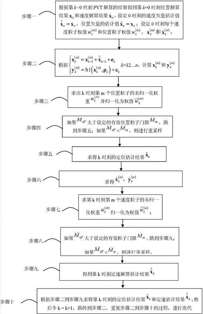
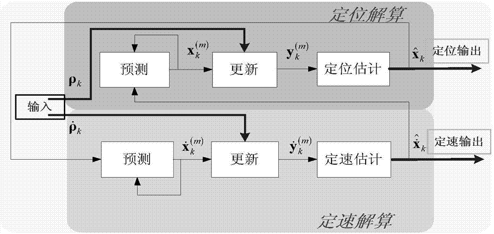
[0026] Specific embodiment one: a kind of GNSS solution method based on block particle filter of this embodiment is specifically carried out according to the following steps:

[0027] Step 1, according to the result of PVT (Position, Velocity, Time) solution at the k=0th moment, the position solution x at the k=0th moment is obtained 0 and velocity solution results Set the velocity vector estimate at time 0 Estimated value of the position vector Set the weight of each speed particle at time 0 and position particle weights make And determine the M four-dimensional position particles at time 0 and M four-dimensional velocity particles in Evenly distributed in around, Evenly distributed in around; define the mth position particle as in respectively represent the three-dimensional coordinates of the mth position particle at time 0, Represents the clock deviation between the state of the mth position particle and the satellite at time 0; define the posit...

specific Embodiment approach 2

[0041] Specific implementation mode two: the difference between this implementation mode and specific implementation mode one is: in step two is the kth moment, the N-dimensional observation vector of the particle at the mth position is defined as:

[0042] y k ( m ) = ρ 1 , k - ( x 1 , k - x U ,...

specific Embodiment approach 3

[0044] Specific embodiment three: the difference between this embodiment and specific embodiment one or two is: ρ k is an N-dimensional pseudorange vector, defined as:

[0045] ρ k =[ρ 1,k ,ρ 2,k ,...,ρ N,k ] T (5)

[0046] The state vector particle passing through the user at the kth moment Calculate the observed pseudorange:

[0047] ρ n , k = ( x n , k - x U , k ) 2 + ( y n , k ...


PUM


Abstract

The invention discloses a GNSS (Global Navigation Satellite System) resolving method based on block particle filter, and relates to a GNSS resolving method of block particle filter. The invention provides a GNSS resolving method based on block particle filter for solving the problems of complicated calculation amount of a traditional linearizing method, higher dimension of an iteration vector in an iteration process, and restriction on precisions of location and constant speed resolving. The GNSS resolving method comprises the following steps: 1, setting parameters described in the specification at a moment 0; 2, calculating parameters X<(m)>k and Y<(m)>k; 3, solving a normalization weight described in the specification; 4, if Meff is more than Mth, skipping to a step 5, and if Meff is less than Mth, re-sampling; 5, solving a location estimation result described in the specification; 6, determining parameters described in the specifications; 7, solving a normalization weight described in the specification; 8, if a parameter described in the specification is more than a parameter described in the specification, skipping to a step 9, and if the parameter described in the specification is less than the parameter described in the specification, re-sampling; 9, performing constant-speed resolving of an estimation result described in the specification at a moment k, and 10, k is equal to k+1, skipping to the step 2, and repeating processes from the step 2 to the step 10. The GNSS resolving method is applied to the field of a GNSS of block particle filter.

Description

technical field [0001] The invention relates to a GNSS calculation method based on block particle filter. Background technique [0002] With the vigorous development of electronic information technology, the core role of Global Navigation Satellite System (GNSS) in location-based services has become more and more significant, which can provide all-weather positioning, speed determination and timing services on a global scale. Applications include aircraft navigation, precision timing, atmospheric monitoring, geological exploration, etc. Due to the continuous progress of hardware technology and theory, people also have higher requirements for the positioning accuracy of GNSS system in positioning and constant speed calculation. [0003] According to the measured pseudo-range and pseudo-range change rate, as well as the satellite position information and velocity information obtained from the ephemeris, the receiver can establish a nonlinear equation system about its own posi...

Claims


Application Information

Patent Timeline
Patent Type & Authority Applications(China)
IPC IPC(8): G01S19/37
CPCG01S19/37
Inventor 韩帅李亚添罗德巳孟维晓
Owner HARBIN INST OF TECH
Why Eureka
Try Eureka