Adaptive blind equalization method based on deviation compensation

An adaptive, blind equalization technology, applied in baseband systems, baseband system components, shaping networks in transmitters/receivers, etc., can solve problems such as impracticability

Active Publication Date: 2017-05-10
BEIJING INSTITUTE OF TECHNOLOGYGY
View PDF4 Cites 9 Cited by
  • Summary
  • Abstract
  • Description
  • Claims
  • Application Information

AI Technical Summary

Problems solved by technology

[0008] The purpose of the present invention is to solve the defect that the existing method of using SOS to realize blind identification and blind equalization cannot be implemented under the condition of additive noise with unknown noise variance in each transmission channel, and proposes an adaptive blind equalization method based on deviation compensation

Method used


Image

  • Adaptive blind equalization method based on deviation compensation
  • Adaptive blind equalization method based on deviation compensation
  • Adaptive blind equalization method based on deviation compensation

Examples


Embodiment 1

[0076] This embodiment describes the process of applying the "Adaptive Blind Equalization Method Based on Offset Compensation" of the present invention to the scenario of two transmission channels.

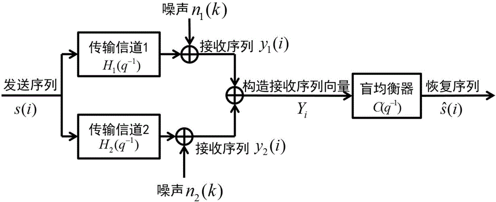
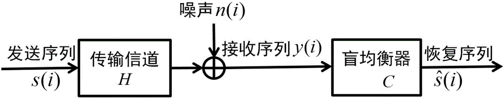
[0077] figure 1 is the transmission channel model adopted in this embodiment, figure 2 The schematic diagram of this method.

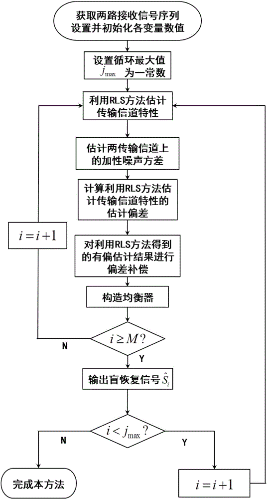
[0078] image 3 It is the algorithm flowchart of this method and the flowchart of this embodiment; As can be seen from the figure, this method comprises the following steps:

[0079]Step A: Obtain two received signal sequences, set and initialize the value of each variable in this method;

[0080] Specifically in this embodiment, the loop count value j is initialized to 1; the loop maximum value is j max ; The channel order L is 3, and the loop count value i is initialized to L+2; P L+1 = δ -1 I L , δ is a very small positive number, and δ=10 in this embodiment -6 ; Smoothing factor M=50; take t / 2 as the sampling interval, alternately sample t...

Embodiment 2

[0114] According to the noise estimation method in Embodiment 1, this embodiment specifically explains the output effect of the noise variance estimation part of this method when the unknown additive noise variances on the two transmission channels are not equal or equal, and the results are as follows Figure 4 shown.

[0115] Among them, case 1 means that when the unknown additive noise variances on the two transmission channels are different, and Estimation of the noise variance; case 2 means when the unknown additive noise variance on the two transmission channels is the same, and An estimate of the noise variance. Depend on Figure 4 In the two cases, we can see that this method can realize the real-time estimation of the additive noise variance on each transmission channel, and no matter whether the additive noise on each transmission channel has the same statistical characteristics, this method can accurately estimate the unknown additive noise. Sexual noise varian...

Embodiment 3

[0117] According to the algorithm flow in embodiment 1, this embodiment further illustrates the effectiveness of the system and algorithm of the present invention through specific examples. Here, specific simulation examples and analysis are given:

[0118] The simulation experiment uses 16-QAM signal as the input signal, the channel noise uses Gaussian white noise, and The channel characteristics of the two transmission channels are shown in formulas (25) and (26) respectively:

[0119] h 1 (q -1 )=-0.6233+1.9054q -1 +(0.6064+0.75i)q -2 -0.6233q -3 (25)

[0120] h 2 (q -1 )=0.2699-0.1558i+(2.1749+0.4764i)q -1 +(-0.8251+0.4763i)q -2 +(0.2699-0.1558i)q -3 (26)

[0121] The number of iterations of the simulation is set to 15000, and the number of independent experiments is set to 100.

[0122] Figure 5 What is given is the estimation accuracy comparison between the RLS method without offset compensation and the RLS method based on offset compensation to estimate...


PUM


Abstract

The invention provides an adaptive blind equalization method based on deviation compensation, and belongs to the technical field of broadband wireless digital communication blind equalization. The adaptive blind equalization method comprises noise variance estimation, blind channel identification deviation compensation, equalizer construction and blind restoration, and comprises the following steps: 1, performing over sampling on received signals at a receiving end to obtain two paths of received signal sequences; 2, estimating transmission channel properties to obtain a biased estimation value of the transmission channel properties; 3, calculating an estimation deviation of the biased estimation value of the transmission channel properties; 4, compensating the biased estimation value to obtain a compensated biased estimation value of the transmission channel properties; 5, constructing an equalizer; 6, constructing a received signal vector, and performing blind restoration on an input signal sequence; and 7, judging whether a cycle counting value reaches the maximum value, and deciding whether the method is accomplished. By adoption of the method, unknown additive noise variances can be estimated in real time, more accurate estimation of the transmission channel properties is obtained, the convergence performance is excellent, and the output precision of the blind equalizer and the anti-interference ability of the system are improved.

Description

technical field [0001] The invention relates to an adaptive blind equalization method, in particular to an adaptive blind equalization method based on bias compensation (Bias Compensation), which belongs to the technical field of broadband wireless digital communication and blind equalization. Background technique [0002] Blind equalization (Blind Equalization) refers to the signal processing technology that the equalizer can use only the received signal sequence to equalize the channel and restore the input signal sequence without the help of the training sequence. In 1975, the Japanese scholar Y. Sato first proposed the concept of "blind equalization", a self-restoring equalization applied to multi-amplitude modulation data transmission. Afterwards, the blind equalization technology became a research hotspot in the communication field, and many methods to solve the blind equalization problem came into being. The early blind equalization method is mainly based on the High...

Claims


Application Information

Patent Timeline
Patent Type & Authority Applications(China)
IPC IPC(8): H04L25/03H04L25/02
CPCH04L25/0238H04L25/03019H04L25/0307
Inventor 贾丽娟娄健
Owner BEIJING INSTITUTE OF TECHNOLOGYGY
Why Eureka
Try Eureka