Novel cable pay-off rack

A pay-off frame and cable technology, which is applied to cable laying equipment, conveying filamentous materials, thin material processing, etc., can solve the problems of high risk, laborious cable reel placed on the top, easy extension of support rods, etc.

Inactive Publication Date: 2014-08-06
国网山东省电力公司沂水县供电公司
View PDF6 Cites 5 Cited by
  • Summary
  • Abstract
  • Description
  • Claims
  • Application Information

AI Technical Summary

Problems solved by technology

In this patent, the optical cable reel is placed on the top, and there are mainly disadvantages: (1) it is necessary to put the cable reel on the top with great effort, and when the cable is relatively heavy, it needs mechanical equipment to lift it to the top; (2) the cable reel is located at the top, Higher risk; (3) The stability of the entire pay-off frame is poor, and it is easily deformed when the cable is quickly unwound, and the support rod is easy to extend outward

Method used


Image

  • Novel cable pay-off rack
  • Novel cable pay-off rack
  • Novel cable pay-off rack

Examples


Embodiment 1

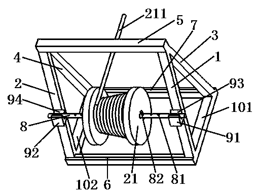
[0026] see figure 1 ; A new type of cable pay-off rack, it includes the first support rod 1, the second support rod 2, the third support rod 3, the fourth support rod 4, the top rod 5, the first fixed rod 6, the second fixed rod The rods 7 and the shaft-shaped bodies 8, the tops of the first support rod and the third support rod are connected to each other and the tops of the second support rod and the fourth support rod are connected by a top rod, characterized in that: The bottom of the first support rod and the second support rod are connected by a first fixing rod, the bottom of the third support rod and the fourth support rod are connected by a second fixing rod, the first support rod and the second support rod are parallel, and the third support rod and the bottom of the fourth support rod are connected by a second fixed rod. The third support rod and the fourth support rod are also parallel, the first support rod and the third support rod are spread apart, the second su...

Embodiment 2

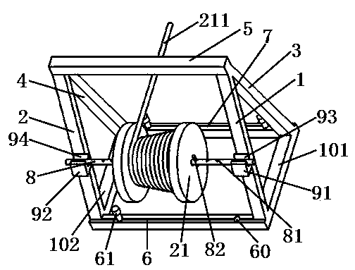
[0028] see figure 2 , and refer to figure 1, a new type of cable pay-off rack, basically the same as the implementation example 1, the difference is: the positioning mechanism of the pay-off rack is the first connecting rod 101 connecting the first supporting rod and the third supporting rod, connecting the second supporting rod The second connecting rod 102 of the rod and the fourth supporting rod, the connecting rod positioning hole 60 located on the first fixing rod and / or the second fixing rod, and the first fixing rod and / or the second fixing rod being fixed through the connecting rod positioning hole The rod is fixed to the connecting rod positioning pin 61.

Embodiment 3

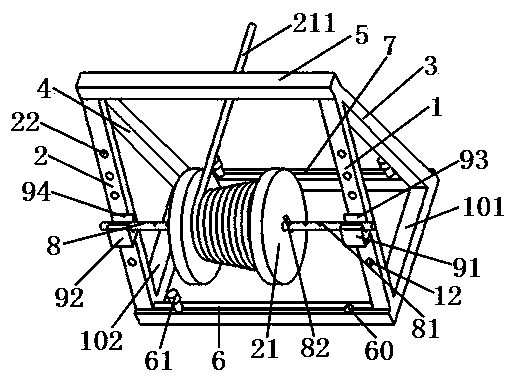
[0030] see image 3 , and refer to figure 2 , a new type of cable pay-off frame, which is basically the same as the implementation example 2, the difference is: the first support rod has a plurality of first bearing frame positioning parts 12, and the second support rod has a plurality of second bearing shafts Frame positioning member 22; the first bearing frame positioning member is a concave hole, and the second bearing frame positioning member is a concave hole; the first bearing frame is fixed on the first support rod through the concave hole, and the second bearing frame positioning member is a concave hole; The two bearing brackets are fixed on the second support rod through a concave hole; the concave hole is a cylindrical hole, of course, it can also be a hole of other shapes, and the concave hole penetrates the first support rod and the second support rod of.

[0031] Of course, when the first bearing frame positioning part is a concave hole, there should be at lea...


PUM


Abstract

The invention belongs to the technical fields of power construction and cables, and particularly relates to a novel cable pay-off rack. The novel cable pay-off rack comprises a first support rod, a second support rod, a third support rod, a fourth support rod, a top rod, a first fixing rod, a second fixing rod and a shaft-shaped body, wherein the junction of the tops of the first support rod and the third support rod is connected with the junction of the tops of the second support rod and the fourth support rod by the top rod. The novel cable pay-off rack is characterized in that the bottoms of the first support rod and the second support rod are connected by the fixing rod; the bottoms of the third support rod and the fourth support rod are connected by the fixing rod; the first support rod and the second support rod are parallel; the third support rod and the fourth support rod are parallel; the first support rod and the third support rod are propped away from each other; the second support rod and the fourth support rod are propped away from each other; shaft-bearing frames are fixed on the first support rod and the second support rod; shaft-bearing grooves are formed in the shaft-bearing frames; a plurality of shaft-shaped body limit holes are formed in the shaft-shaped body; the cable pay-off rack is further provided with a cable pay-off rack location mechanism for fixing the position thereof. The novel cable pay-off rack disclosed by the invention has the following main beneficial effects: cable pay-off is more labour-saving, cable pay-off is more stable, and the pay-off rack is easier to carry.

Description

technical field [0001] The invention belongs to the field of electric power construction and cable technology, and in particular relates to a novel cable pay-off frame. Background technique [0002] In electric power construction, it is often necessary to release the cables from the reel. However, the pay-off racks in the prior art are difficult to satisfy the effect of stable cable release in the construction field. For example, the patent title is: a novel optical cable pay-off rack, the Chinese patent whose authorized announcement number is CN203324549U discloses a new type of optical cable pay-off rack, which includes a first support rod (3), a second support rod (4 ), the third support rod (10) and the fourth support rod (11), the first support rod (2) is fixed between the first support rod (3) and the third support rod (10), the second support rod ( 4) and the fourth support rod (11) are fixed with the second fixed rod (6); the apex intersection of the first support r...

Claims


Application Information

Patent Timeline
Patent Type & Authority Applications(China)
IPC IPC(8): H02G1/06B65H49/30B65H49/32
Inventor 戴丽芬
Owner 国网山东省电力公司沂水县供电公司
Why Eureka
Try Eureka