Intermediate oil supply device of fuel system
A fuel supply device and fuel system technology, applied in the aviation field, can solve the problems of difficulty in meeting requirements, insufficient stability, simple structure, etc., and achieve the effects of high stability, ensuring normal and stable operation, and simple and reliable structure
- Summary
- Abstract
- Description
- Claims
- Application Information
AI Technical Summary
Problems solved by technology
Method used
Image
Examples
Embodiment 1
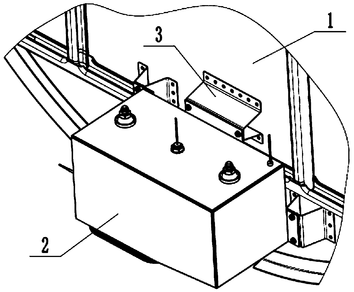
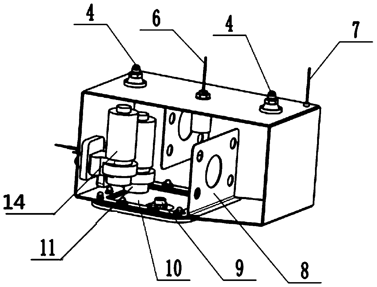
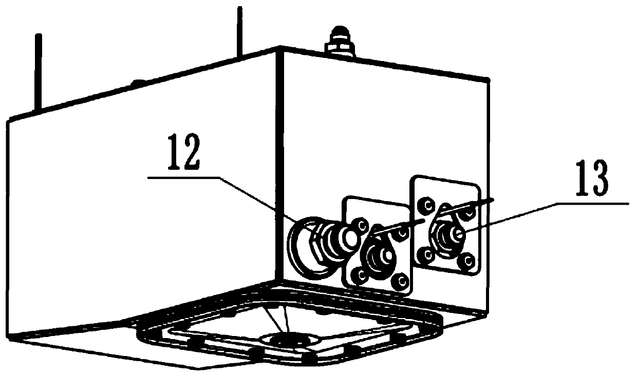
[0032] Such as Figure 1-3 As shown, the present invention provides a technical solution: comprising a tank body 2, an oil inlet 12 and an oil outlet 13 arranged on one side of the tank body, and a booster device and a fuel grid arranged inside the tank body 2 Blocking device 8;
[0033] The oil inlet 12 communicates with the tank 2; the booster device communicates with the oil outlet 13;
[0034] Said supercharging device comprises a first supercharging device 11 and a second supercharging device 14;
[0035] The first pressurization device 11 and the second pressurization device 14 are arranged vertically and staggered.
[0036] Specifically, the number of boosting devices is more than 2, and the model is ZC6-8 / RLB-82. The electric fuel booster pump has a pressure sensing function, which can transmit the pressure signal in the oil pump to the control motor, so as to Control the start and stop of the oil pump; the first supercharging device 11 and the second supercharging ...
Embodiment 2
[0041] Such as Figure 1-4 As shown, the present invention provides a technical solution: comprising a tank body 2, an oil inlet 12 and an oil outlet 13 arranged on one side of the tank body, and a booster device and a fuel grid arranged inside the tank body 2 Blocking device 8;
[0042] The oil inlet 12 communicates with the tank 2; the booster device communicates with the oil outlet 13;
[0043] Said supercharging device comprises a first supercharging device 11 and a second supercharging device 14;
[0044] The first pressurization device 11 and the second pressurization device 14 are arranged vertically and staggered.
[0045] Specifically, an anti-leakage device 6 is provided on the top of the box body 2; one end of the anti-leakage device 6 communicates with the outside of the box body; the other end of the anti-leakage device 6 communicates with the inside of the box body.
[0046] Specifically as Figure 4 As shown, the anti-leakage device 6 is a GF5500-401 float s...
Embodiment 3
[0050] Such as Figure 1-5 As shown, the present invention provides a technical solution: comprising a tank body 2, an oil inlet 12 and an oil outlet 13 arranged on one side of the tank body, and a booster device and a fuel grid arranged inside the tank body 2 Blocking device 8;
[0051] The oil inlet 12 communicates with the tank 2; the booster device communicates with the oil outlet 13;
[0052] Said supercharging device comprises a first supercharging device 11 and a second supercharging device 14;
[0053] The first pressurization device 11 and the second pressurization device 14 are arranged vertically and staggered.
[0054] Specifically, an alarm system is also included, and the alarm system includes an alarm device arranged on the top of the box body 2 , a controller 600 connected to the alarm device 7 , and an alarm indicator light 601 connected to the controller 600 . The alarm device 7 is an electronic liquid level sensor, which is connected to the cab controller 6...
PUM
| Property | Measurement | Unit |
|---|---|---|
| Nominal diameter | aaaaa | aaaaa |
Abstract
Description
Claims
Application Information
 - R&D
- Intellectual Property
- Life Sciences
- Materials
- Tech Scout
- Unparalleled Data Quality
- Higher Quality Content
- 60% Fewer Hallucinations
Browse by: Latest US Patents, China's latest patents, Technical Efficacy Thesaurus, Application Domain, Technology Topic, Popular Technical Reports.
© 2025 PatSnap. All rights reserved.Legal|Privacy policy|Modern Slavery Act Transparency Statement|Sitemap|About US| Contact US: help@patsnap.com


