AI technical title is built by PatSnap AI team. It summarizes the technical point description of the patent document.
A pay-off rack and cable technology, used in cable laying equipment, conveying filamentous materials, thin material handling, etc., can solve the problems of easy deformation, high risk, and easy extension of support rods.
Inactive Publication Date: 2016-09-07
国网山东省电力公司沂水县供电公司
View PDF6 Cites 1 Cited by
Summary
Abstract
Description
Claims
Application Information
AI Technical Summary
This helps you quickly interpret patents by identifying the three key elements:
Problems solved by technology
Method used
Benefits of technology
Problems solved by technology
In this patent, the optical cable reel is placed on the top, and there are mainly disadvantages: (1) it is necessary to put the cable reel on the top with great effort, and when the cable is relatively heavy, it needs mechanical equipment to lift it to the top; (2) the cable reel is located at the top, Higher risk; (3) The stability of the entire pay-off frame is poor, and it is easily deformed when the cable is quickly unwound, and the support rod is easy to extend outward
Method used
Image
Click on the blue label to locate the original text in one second.
Reading with bidirectional positioning of images and text.
Examples
Embodiment 1
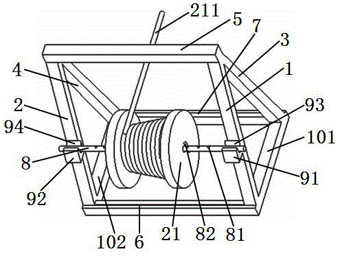
[0025] please see figure 1; A cable pay-off rack, which includes a first support rod 1, a second support rod 2, a third support rod 3, a fourth support rod 4, a push rod 5, a first fixed rod 6, a second fixed rod 7 , shaft-shaped body 8, the top of the first support bar, the third support bar and the top of the second support bar, the fourth support bar are connected by a push rod between the intersection, it is characterized in that: the first The bottom of the support rod and the second support rod is connected by the first fixed rod, the bottom of the third support rod and the fourth support rod is connected by the second fixed rod, the first support rod is parallel to the second support rod, and the third support rod The rod and the fourth support rod are also parallel, the first support rod and the third support rod are stretched apart, the second support rod and the fourth support rod are stretched apart, and the first support rod is fixed with the first support rod. A ...
Embodiment 2
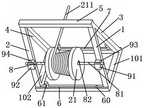
[0027] please see figure 2 , and refer to figure 1 , a cable pay-off frame, basically the same as the implementation example 1, the difference is: the positioning mechanism of the pay-off frame is a first connecting rod 101 connecting the first support rod and the third support rod, connecting the second support rod and the third support rod The second connecting rod 102 of the fourth support rod, the connecting rod positioning hole 60 on the first fixing rod and / or the second fixing rod, and the first fixing rod and / or the second fixing rod are fixed through the connecting rod positioning hole The connecting rod positioning pin 61.
Embodiment 3
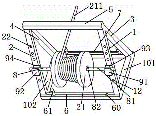
[0029] please see image 3 , and refer to figure 2 , a cable pay-off frame, basically the same as the implementation example 2, the difference is that there are a plurality of first bearing frame positioning parts 12 on the first support rod, and a plurality of second bearing frame positioning parts 12 on the second support rod. Part 22; the first bearing frame positioning part is a concave hole, and the second bearing frame positioning part is a concave hole; the first bearing frame is fixed on the first support rod through the concave hole, and the second bearing The axle frame is fixed on the second support rod through the concave hole; the concave hole is a cylindrical hole, of course, it can also be a hole of other shapes, and the concave hole runs through the first support rod and the second support rod.
[0030] Of course, when the first bearing frame positioning part is a concave hole, there should be at least one; when the second bearing frame positioning part is ...
PUM
Abstract
The invention belongs to the technical fields of power construction and cables, and particularly relates to a novel cable pay-off rack. The novel cable pay-off rack comprises a first support rod, a second support rod, a third support rod, a fourth support rod, a top rod, a first fixing rod, a second fixing rod and a shaft-shaped body, wherein the junction of the tops of the first support rod and the third support rod is connected with the junction of the tops of the second support rod and the fourth support rod by the top rod. The novel cable pay-off rack is characterized in that the bottoms of the first support rod and the second support rod are connected by the fixing rod; the bottoms of the third support rod and the fourth support rod are connected by the fixing rod; the first support rod and the second support rod are parallel; the third support rod and the fourth support rod are parallel; the first support rod and the third support rod are propped away from each other; the second support rod and the fourth support rod are propped away from each other; shaft-bearing frames are fixed on the first support rod and the second support rod; shaft-bearing grooves are formed in the shaft-bearing frames; a plurality of shaft-shaped body limit holes are formed in the shaft-shaped body; the cable pay-off rack is further provided with a cable pay-off rack location mechanism for fixing the position thereof. The novel cable pay-off rack disclosed by the invention has the following main beneficial effects: cable pay-off is more labour-saving, cable pay-off is more stable, and the pay-off rack is easier to carry.
Description
technical field [0001] The invention belongs to the field of electric power construction and cable technology, and in particular relates to a cable pay-off frame. Background technique [0002] In electric power construction, it is often necessary to release the cables from the reel. However, the pay-off racks in the prior art are difficult to satisfy the effect of stable cable release in the construction field. For example, the patent title is: a novel optical cable pay-off rack, the Chinese patent whose authorized announcement number is CN203324549U discloses a new type of optical cable pay-off rack, which includes a first support rod (3), a second support rod (4 ), the third support rod (10) and the fourth support rod (11), the first support rod (2) is fixed between the first support rod (3) and the third support rod (10), the second support rod ( 4) and the fourth support rod (11) are fixed with the second fixed rod (6); the apex intersection of the first support rod (...
Claims
Application Information
Patent Timeline
Application Date:The date an application was filed.
Publication Date:The date a patent or application was officially published.
First Publication Date:The earliest publication date of a patent with the same application number.
Issue Date:Publication date of the patent grant document.
PCT Entry Date:The Entry date of PCT National Phase.
Estimated Expiry Date:The statutory expiry date of a patent right according to the Patent Law, and it is the longest term of protection that the patent right can achieve without the termination of the patent right due to other reasons(Term extension factor has been taken into account ).
Invalid Date:Actual expiry date is based on effective date or publication date of legal transaction data of invalid patent.

