Mounting member, and seat equipped with airbag module

A technology for installing parts and airbags, applied to seat frames, vehicle parts, vehicle seats, etc., can solve the problems of time-consuming and other problems, and achieve the effect of simple structure, high deployment performance, and simple assembly operation

Active Publication Date: 2014-08-06
TS TECH CO LTD
View PDF6 Cites 3 Cited by
  • Summary
  • Abstract
  • Description
  • Claims
  • Application Information

AI Technical Summary

Problems solved by technology

[0010] Furthermore, in the process of setting the end of the fabric made of soft cloth, dexterity of the fingers is required, and it may take time.

Method used


Image

  • Mounting member, and seat equipped with airbag module
  • Mounting member, and seat equipped with airbag module
  • Mounting member, and seat equipped with airbag module

Examples


Embodiment 1

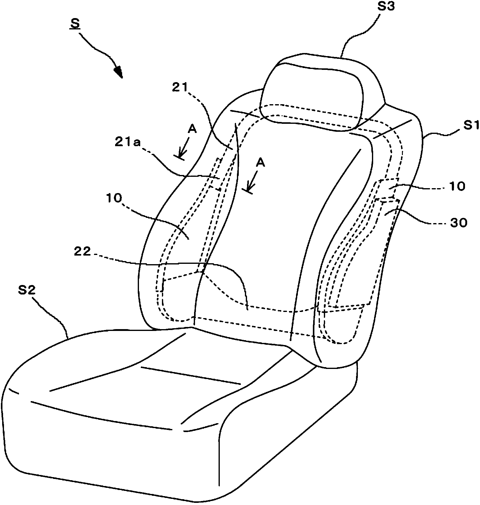
[0113] Such as figure 1 As shown, the vehicle seat S according to this embodiment is composed of a seat back S1 , a seat portion S2 , and a headrest S3 .

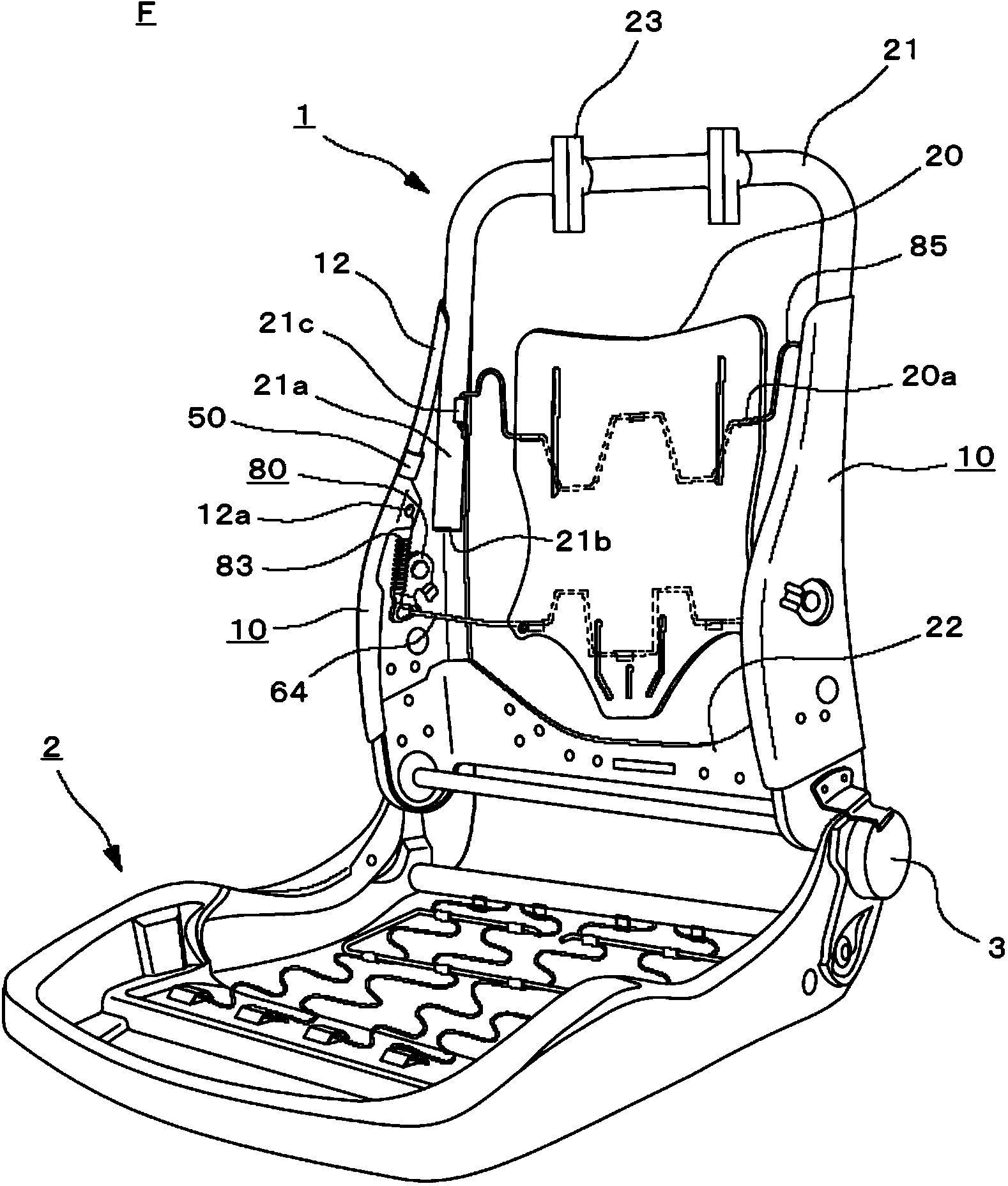
[0114] figure 2 The seat frame F shown is provided in a vehicle seat S. As shown in FIG. The seat frame F is composed of a seat back frame 1 as a frame of the seat back S1 and a seat frame 2 as a frame of the seat portion S2. The seat frame 2 and the seat back frame 1 are connected by a reclining mechanism 3 . The seat back S1 and the seat portion S2 are constituted by a cushion and a decorative cover provided on the outer sides of the seat back frame 1 and the seat frame 2 .

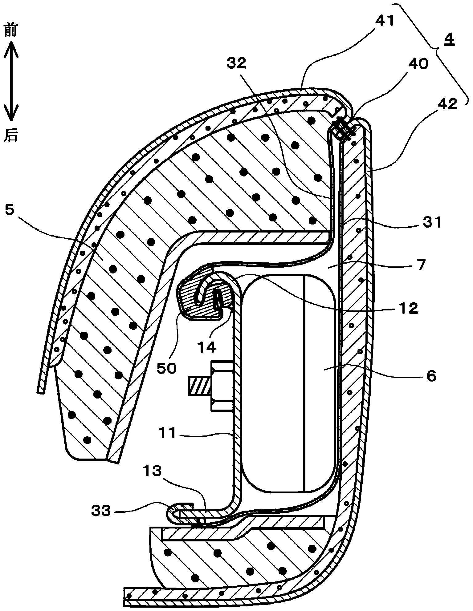
[0115] Such as figure 1 , figure 2 As shown, the seat frame S1 consists of the seat back frame 1, the cushion pad 5 placed on the seat back frame 1, the decorative cover 4 covering the seat back frame 1 and the cushion pad 5, and the broken part of the decorative cover 4 sewn on one end. The pair of fabrics 31 and 32 of the part 40 are main c...

Embodiment 2

[0179] according to Figure 17 ~ Figure 19 A second embodiment of the present invention will be described. In addition, description of the same configuration as that of the first embodiment is omitted.

[0180] Instead of the mounting part 50 of Embodiment 1, it is also possible to use Figure 17 ~ Figure 19 Mounting part 50 is shown.

[0181] In the attachment member 50 of this embodiment, the opening connected to the slit 69 is formed between the inner wall surface 59i and the curved surface 55b.

[0182] The slit 69 is provided at a position opposite to the groove 53 on the side wall of the locking portion 55 , and is an opening extending to the outer surface of the mounting member 50 . The gap surrounded by the first wall portion 59 and the second wall portion 60 constitute.

[0183] The first wall portion 59 extends from the curved surface 55a, and the second wall portion 60 extends from the curved surface 55b. The second wall portion 60 is opposed to the end portion...

Embodiment 3

[0219] refer to Figure 20 ~ Figure 24 A third embodiment of the present invention will be described. In addition, description of the same configuration as that of the first embodiment is omitted.

[0220] In the side frame 10 of the present embodiment, as Figure 20 As shown, the front edge portion 12 includes an upper portion 12a, a large curvature portion 12b, and a lower portion 12c. The upper part 12a is a part sandwiched between the upper end of the front edge part 12 and the large curvature part 12b, and the distance from the rear edge part 13 is substantially constant, or the lower part is located slightly away from the rear edge part 13 than the upper part.

[0221] The large curvature part 12b is a part sandwiched between the upper part 12a and the lower part 12c, and is a part where the distance from the rear edge part 13 increases rapidly. The large curvature portion 12b is drawn as a concave curve toward the rear of the seat S when viewed from the side. Over t...


PUM


Abstract

Provided are: a clip member which enables the periphery of a portion to which stay cloth is mounted can be made compact while high expansion performance of the airbag is maintained and which can be easily mounted; and a seat equipped with an airbag module, the seat being provided with the clip member. A clip member (50) is connected to a cloth-like body (32) for transmitting a tensile force. The clip member (50) is provided with a connection section (55) which is connected to one end of the cloth-like body (32), and a groove (53) which is engaged with an end (12) of a mounting section (10). The clip member (50) is provided so that, when engaged with the end (12) of the mounting section (10), the clip member (50) reduces a rotational force generated in the connection section (55) by a tensile force transmitted from the cloth-like member (32) and connects the cloth-like body (32) and the mounting section (10).

Description

technical field [0001] The present invention relates to a clip member and an airbag module-equipped seat, and relates to a clip member and an airbag module-equipped seat for locking a fabric wrapping an airbag module provided on a side portion of a seat back. Background technique [0002] Currently, a seat equipped with an airbag module is a seat in which the airbag is attached to the side frame of the seat back frame, and each end of the trim cover is sewn together with the edge ends of two pieces of fabric to form a broken part of the trim cover , by wrapping the airbag module with two pieces of fabric drawn into the interior of the trim cover from the breakage, and encapsulating the entire seat back including the airbag module with the trim cover (for example, Patent Documents 1 and 2). [0003] In Patent Document 1, on the opposite side of the airbag module of the side frame, two hanging wires are arranged to be intertwined into a smart loop. The ends of the two pieces ...

Claims


Application Information

Patent Timeline
IPC IPC(8): B60R21/207B60N2/427
CPCB60N2/5841B60N2/5825B60N2002/5808B60N2/66F16B2/22B60N2/72B60R2021/2076F16B5/0692B60R21/207B60N2/68B60N2/427
Inventor 田边仁一伊泽启史马场广
Owner TS TECH CO LTD
Why Eureka
Try Eureka