Pipe cutting and grooving machine

A groove machine and cutting groove technology, applied in metal processing and other directions, can solve the problems of uneven cutting surface and cumbersome grooves, and achieve the effect of compact design structure and stable operation

Active Publication Date: 2014-08-13
HENAN ZHONGZE NEW MATERIAL
View PDF8 Cites 7 Cited by
  • Summary
  • Abstract
  • Description
  • Claims
  • Application Information

AI Technical Summary

Problems solved by technology

[0005] The purpose of the present invention is to overcome the deficiencies of the prior art, to meet the needs of reality, and to provide a pipe cutting and groove machine, ai

Method used


Image

  • Pipe cutting and grooving machine
  • Pipe cutting and grooving machine
  • Pipe cutting and grooving machine

Examples


Embodiment 1

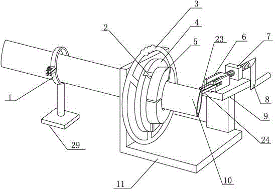
[0039] Embodiment 1: a kind of pipe material cutting, groove machine, see Figure 1 to Figure 8 , including a frame 11, a clamping and rotating mechanism for clamping and rotating the pipe, a cutting groove mechanism for cutting and grooves on the pipe, and a power source correspondingly arranged on the bracket 11;

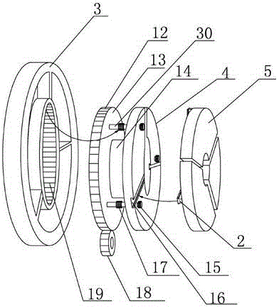
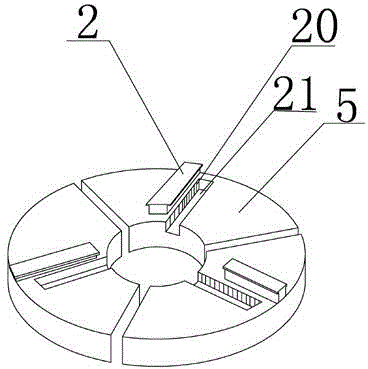
[0040] Such as figure 2 As shown, the clamping and rotating mechanism includes a fixed cylinder 14 with openings at both ends, a main power wheel 13 arranged correspondingly from left to right, a clamping driving wheel 3, a slave power wheel 4, and three round openings connected in the middle. Holder 5; the middle part of the main power wheel 13 is provided with a circular opening and communicates with one end of the fixed cylinder 14, and a rack 12 is provided on the main power wheel 13, and a Below is provided with the main gear 18 meshed with the main power wheel, and the main gear 18 is correspondingly connected with the power source; as Figure 7 As shown,...


PUM


Abstract

The invention relates to a pipe cutting and grooving machine which aims at solving the technical problems that the cutting surfaces are uneven and the construction requirements are not met due to the existing manual cutting on plastic pipes and grooving on the pipes is complicated in technology. The pipe cutting and grooving machine comprises a frame, a clamping rotation mechanism, a cutting and grooving mechanism and a power source; the clamping rotation mechanism, the cutting and grooving mechanism and the power source are correspondingly arranged on the frame in turn; the clamping rotation mechanism is used for clamping the pipes and driving the pipes to rotate. According to the pipe cutting and grooving machine, the cutting and grooving machining on the pipes can be effectively and rapidly achieved, the surfaces of the grooved and cut pipes are neat and smooth, and the construction requirements are met.

Description

technical field [0001] The invention relates to a pipe cutting and grooving machine, in particular to a pipe cutting and grooving machine for plastic pipes. Background technique [0002] At present, most of the methods used when cutting plastic pipes are to use hand saws and electric saws to cut them. When cutting with hand saws, there are disadvantages such as uneven cutting surface, time-consuming and laborious, etc., which cannot meet the requirements of high construction precision. At the same time When cutting with a hand saw, there is also the problem that the pipe cannot be effectively fixed; for some cut pipes, it is sometimes necessary to groove the end of the pipe to facilitate subsequent butt joint installation, and the current groove technology mostly uses It is a method of slotting on the machine tool and then transporting it to the construction site. This method is cumbersome to operate and the construction remains unchanged, which cannot effectively solve the ...

Claims


Application Information

Patent Timeline
IPC IPC(8): B26D1/04B26D7/02B26D5/10B26D3/06
Inventor 温殿辉
Owner HENAN ZHONGZE NEW MATERIAL
Why Eureka
Try Eureka