Speed reducer and stirring machinery

A technology of reducer and mixing body, which is applied in the direction of mechanical equipment, transmission parts, gear transmission, etc., can solve the problems of low transmission efficiency, achieve high transmission efficiency, solve low transmission efficiency, transmission stages and gear meshing effect on less

Active Publication Date: 2014-08-13
XUZHOU XCMG CONSTR MACHINERY CO LTD BUILDING MACHINERY
View PDF5 Cites 5 Cited by
  • Summary
  • Abstract
  • Description
  • Claims
  • Application Information

AI Technical Summary

Problems solved by technology

[0007] One of the objectives of the present invention is to propose a speed reducer and a mixing machine equipped with the speed reducer, which solves the technical problem of low transmission efficiency in the prior art

Method used


Image

  • Speed reducer and stirring machinery
  • Speed reducer and stirring machinery
  • Speed reducer and stirring machinery

Examples


Embodiment Construction

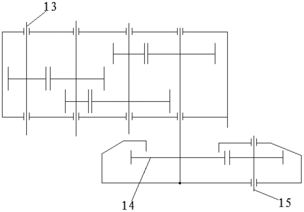
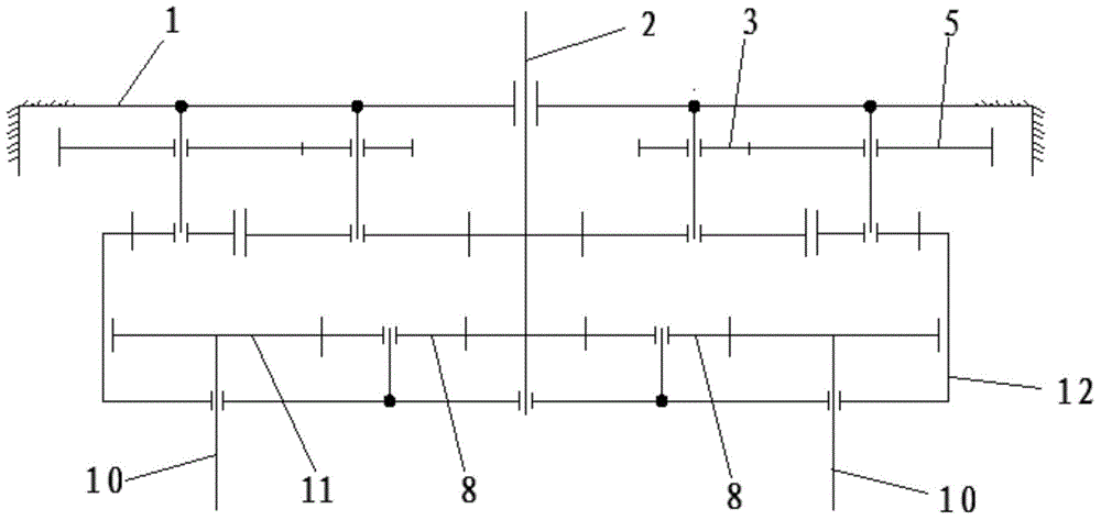
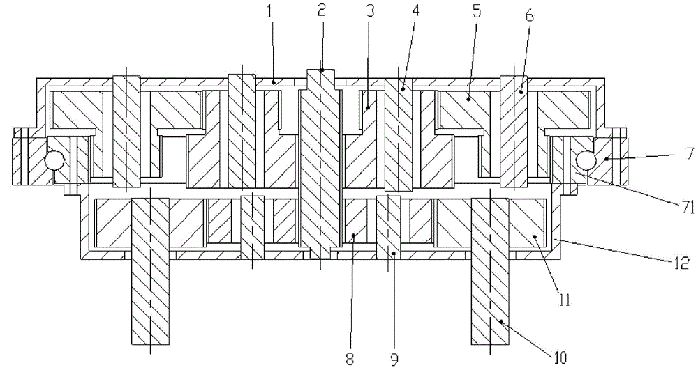
[0046] Below you can refer to the accompanying drawings Figure 1 ~ Figure 3 And the content of the text to understand the content of the present invention and the differences between the present invention and the prior art. The technical solution (including the preferred technical solution) of the present invention will be further described in detail below by means of the accompanying drawings and by way of listing some optional embodiments of the present invention. It should be noted that: any technical feature and any technical solution in this embodiment are one or more of a variety of optional technical features or optional technical solutions. Citing all the alternative technical features and alternative technical solutions of the present invention, it is not convenient for the implementation of each technical feature to emphasize that it is one of the optional multiple implementation modes, so those skilled in the art should know that: Replace any technical means provi...


PUM


Abstract

The invention discloses a speed reducer and stirring machinery, relates to the technical field of engineering machinery and solves the technical problem that the transmission efficiency is low in the prior art. The speed reducer comprises a fixing body, an input gear shaft, a second level duplex gear, a third level duplex gear, an inner gear and a revolution power output part; gear teeth of the input gear shaft and gear teeth of the second level duplex gear are engaged; gear teeth of the second level duplex gear and gear teeth of the third level duplex gear are engaged; gear teeth of the third level duplex gear and gear teeth of the inner gear are engaged; the inner gear and the revolution power output part are fixedly connected or in an integral structure. The stirring machinery comprises a first stirring body, a second stirring body and the speed reducer. The speed reducer improves the transmission efficiency and the sealing performance.

Description

technical field [0001] The invention relates to the technical field of engineering machinery, in particular to a speed reducer and a mixing machine provided with the speed reducer. Background technique [0002] In a mixing machine, in order to make the material mix more evenly, the transmission mechanism usually has two outputs of rotation and revolution. [0003] Such as figure 1 As shown, in the transmission mechanism in the existing reducer, its power input shaft 13 is decelerated by multi-stage parallel shafts ( figure 1 The 3-stage parallel shaft deceleration is shown in the figure) to make the mechanism output a slower revolution speed, and at the same time, a speed-up mechanism 14 is added on the basis of the revolution, so that the transmission mechanism has a faster rotation speed, and the self-transmission power is passed through the power output shaft 15 outputs, so that the whole mechanism can have revolution and rotation output at the same time. [0004] The ...

Claims


Application Information

Patent Timeline
Patent Type & Authority Applications(China)
IPC IPC(8): F16H1/28F16H57/023F16H57/029F16H57/08
CPCF16H1/28F16H57/023F16H57/029F16H57/08F16H2057/02086
Inventor 汤传彬樊学勇张承信王松黄元
Owner XUZHOU XCMG CONSTR MACHINERY CO LTD BUILDING MACHINERY
Why Eureka
Try Eureka