An automatic transmission device and a transmission shaft including a torque-limiting clutch

A technology of automatic transmission device and clutch, applied in the direction of clutch, transmission device, automatic clutch, etc., can solve the problems of complex structure, inability to realize reverse output, and high manufacturing cost

Inactive Publication Date: 2016-04-20
傅元才
View PDF5 Cites 0 Cited by
  • Summary
  • Abstract
  • Description
  • Claims
  • Application Information

AI Technical Summary

Problems solved by technology

[0004] In the prior art, although some transmission devices that realize automatic shifting through torque-limiting clutches and one-way clutches have also appeared, they usually have the disadvantages of complex structure and high manufacturing cost; in addition, reverse output cannot be realized.

Method used


Image

  • An automatic transmission device and a transmission shaft including a torque-limiting clutch
  • An automatic transmission device and a transmission shaft including a torque-limiting clutch
  • An automatic transmission device and a transmission shaft including a torque-limiting clutch

Examples


Embodiment 1

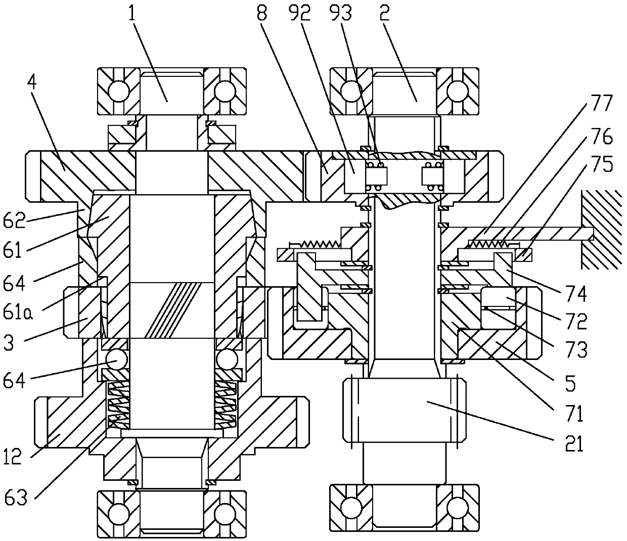
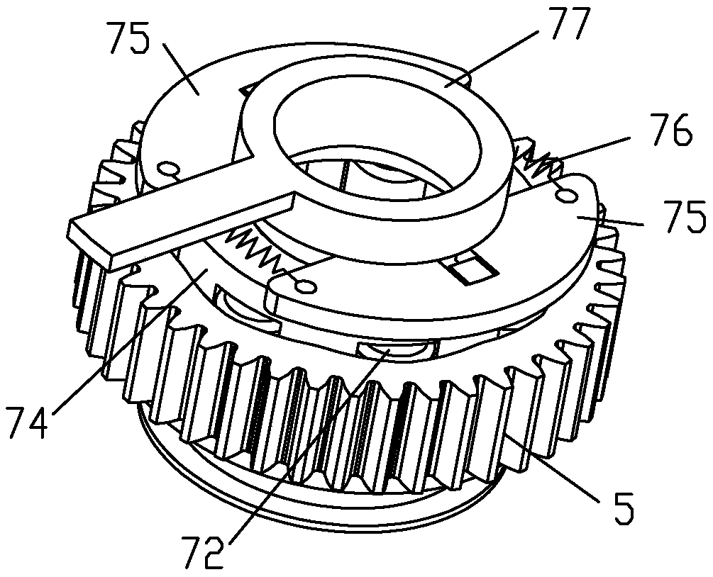
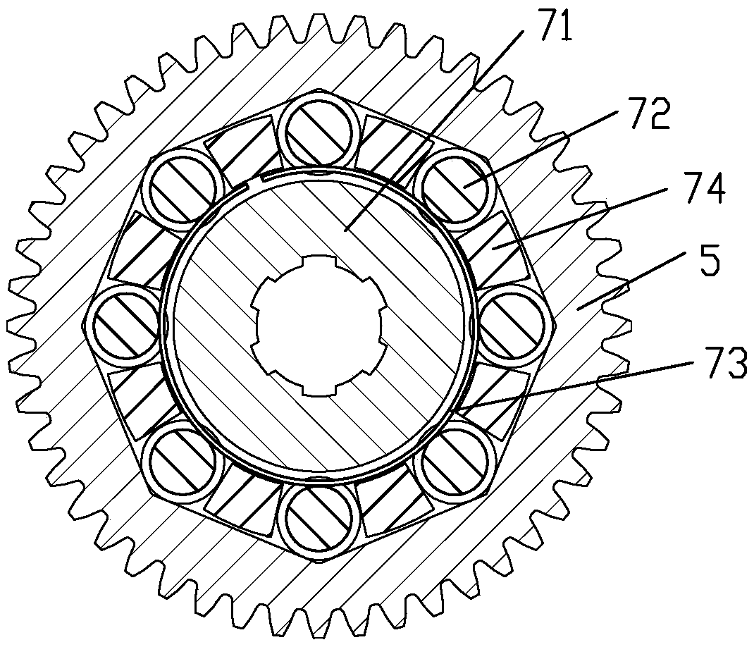
[0042] Example 1 see figure 1 , figure 2 , image 3 , Figure 4, Figure 5 , an automatic transmission device containing a torque-limiting clutch, comprising a driving shaft 1 and a driven shaft 2, the driving shaft 1 and the driven shaft 2 are respectively provided with a pair of high-speed gears and a pair of low-speed gears corresponding to constant meshing, said The high-speed driving gear 4 of the high-speed gear pair is rotatably connected to the drive shaft 1, and a normally closed conical disc friction torque-limiting clutch is arranged between the high-speed gear driving gear 4 and the drive shaft 1. The loading spring 63 is connected between a journal end face of the driving shaft 1 and an end face of the driving cone 61 of the friction torque limiting clutch, and an end face bearing 64 is arranged between the driving cone 61 and the loading spring 63; the driving cone 61 There is also a torque transmission structure for power transmission between the drive shaf...

Embodiment 2

[0053] Example 2 see Figure 6 , Figure 7 , the low gear drive gear 3 is integrated with the drive cone 61; the end face bearing 64 is connected between the loading spring 63 and the low gear drive gear 3; the drive cone 61 is connected to the drive shaft 1 There is a torque transmission structure for power transmission between them. The torque transmission structure is an end face cam pair structure, including the cam pair driving part 11 fixedly connected to the driving shaft 1, which is integrally formed on the driving cone 61 of the friction torque limiting clutch. The cam pair passive part 41 on the cam pair is equipped with a V-shaped groove cam surface on the opposite end faces of the cam pair active part 11 and the cam pair passive part 41, and the protruding parts of the end faces of the active part 11 and the passive part 41 of the cam pair The depressions of the V-shaped groove are complementary, and the slopes on both sides of the V-shaped groove are symmetrical....

Embodiment 3

[0056] Embodiment 3 see Figure 8 , the low gear driving gear 3 is coaxially fixedly connected to the driving shaft 1; the power input gear 12 is fixedly connected to the driving cone 61 of the friction torque limiting clutch; the driving cone 61 is connected to the driving shaft 1 The torque transmission structure of the helical spline fit structure is also provided between the power input gear 12 and the drive shaft 1; the loading spring 63 is connected between the drive cone 61 and the shoulder of the drive shaft 1.

[0057] The rest of the structure of this embodiment is the same as that of Embodiment 1, and will not be repeated here.


PUM


Abstract

The invention discloses an automatic speed change gear with a torsion limiting clutch and a speed change shaft. The speed change gear comprises a high-speed drive gear, a low-speed drive gear, a high-speed driven gear and a low-speed driven gear, wherein the high-speed drive gear and the low-speed drive gear are arranged on a drive shaft, the high-speed driven gear and the low-speed driven gear are arranged on a driven shaft, and the high-speed drive gear, the low-speed drive gear, the high-speed driven gear and the low-speed driven gear are correspondingly and constantly meshed. The drive shaft is provided with the normally-closed torsion limiting clutch used for power connection of the high-speed drive gear and the drive shaft. A connection structure capable of synchronously rotating is formed by the low-speed drive gear and the drive shaft. A one-way overrunning clutch or a two-way overrunning clutch is arranged between the high-speed driven gear and the driven shaft and between the low-speed driven gear and the driven shaft respectively. The speed change shaft comprises the drive shaft, the high-speed drive gear, the low-speed drive gear and the normally-closed torsion limiting clutch, wherein the high-speed drive gear and the low-speed drive gear are arranged on the drive shaft and the normally-closed torsion limiting clutch is used for power transmission between the high-speed drive gear and the drive shaft. The drive end of the clutch is connected with the drive shaft through a spiral spline structure. The automatic speed change gear and the speed change shaft have the advantages that the speed change gear enables the automatic two-gear shifting function of forward transmission and the inverted transmission function to be achieved and is simple in structure and rapid in gear shifting; the high-speed inverted output torsion of the speed change shaft is larger than the forward output torsion.

Description

technical field [0001] The invention relates to a speed change device for a transmission box of an electric vehicle, in particular to an automatic speed change device and a speed change shaft for the transmission box of an electric vehicle including a torque-limiting clutch. Background technique [0002] In this application, an electric vehicle refers to a motorcycle driven by a motor, including two-wheel, three-wheel and four-wheel, and the speed change is mainly realized by controlling the speed of the motor through a controller. With the development of electric vehicle technology, some electric vehicles are currently equipped with gear transmissions with mechanical structures, which mainly provide shifting execution power through electromagnets, etc., and the actuators are driven by electromagnets to achieve shifting. Shifting is usually done by Cyclists operate. Most of the mechanical gear shifting or electronically controlled gear shifting of existing electric vehicles...

Claims


Application Information

Patent Timeline
Patent Type & Authority Patents(China)
IPC IPC(8): F16H3/10F16H61/14F16D43/20
CPCF16D43/218F16H3/10F16H59/14F16H61/148F16H2059/144
Inventor 傅元才刘洪
Owner 傅元才
Why Eureka
Try Eureka