

Ground accelerating moving target imaging method based on quadratic fit range equation
A distance equation, quadratic fitting technology, applied in the field of radar, can solve problems such as failure to propose and large amount of calculation
Inactive Publication Date: 2014-08-13
XIDIAN UNIV
View PDF5 Cites 9 Cited by
- Summary
- Abstract
- Description
- Claims
- Application Information
AI Technical Summary
Problems solved by technology
For the first time, J. Sharma from Canada studied the influence of target acceleration on the performance of target motion parameter estimation in SAR-GMTI system through theoretical analysis and practical experiments, but failed to propose a ground acceleration moving target imaging technology
At present, Yang proposed an imaging method for ground-accelerated moving targets, which uses hough transform technology and partial Fourier transform technology. Applications
Method used
View moreImage
Smart ImageViewing Examples

Examples
Embodiment Construction
Login to View More PUM
 Abstract
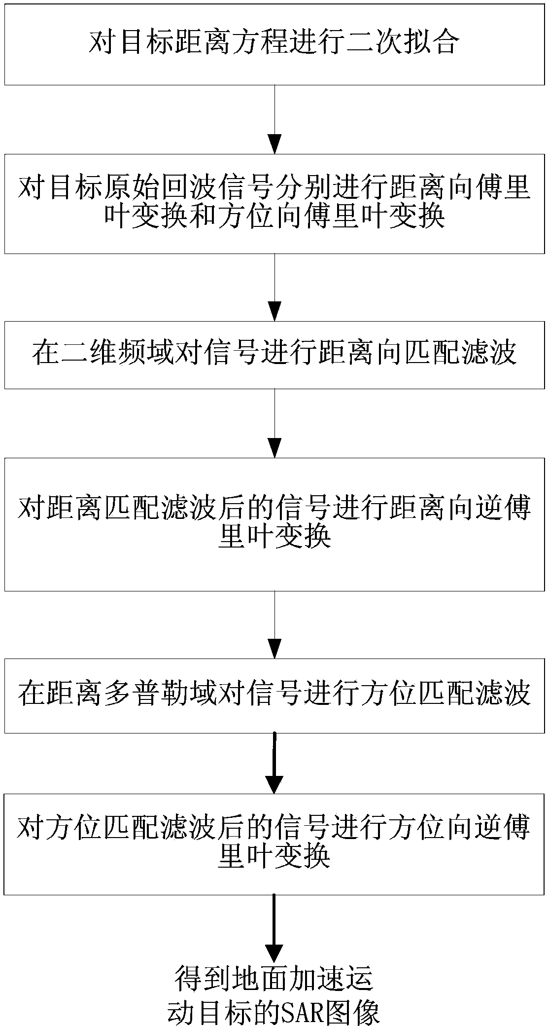
The invention belongs to the technical field of radar, and discloses a ground accelerating moving target imaging method based on a quadratic fit range equation. The method is used for imaging a ground accelerating moving target through synthetic aperture radar. The method includes the steps that (1) quadratic fit is carried out on a target range equation, (2) an original echo signal of the target is changed into a two-dimensional frequency domain, (3) according to the fitted secondary range equation, a range matching filter is built in the two-dimensional frequency domain and range compression and range cell migration correction are carried out, (4) the signal after range compression and range cell migration correction is changed into a range Doppler domain, (5) an azimuth matching filter is built in the range Doppler domain and direction compression is carried out, (6) azimuth inverse discrete fourier transform is carried out on the signal after direction compression, and imaging of the target is finished. Precise imaging of the ground accelerating moving target can be achieved without the need of knowing speed parameters, position parameters and the acceleration speed of the target, and calculation efficiency is high.
Description
technical field The invention belongs to the field of radar technology, in particular to a method for imaging ground accelerating moving targets based on a quadratic fitting distance equation, which is used for synthetic aperture radar (SAR) imaging of ground accelerating moving targets. Background technique Synthetic Aperture Radar (SAR) is an active system that uses electromagnetic waves in the microwave spectrum as a detection carrier to observe surface features. SAR has the characteristics of two-dimensional high-resolution, all-weather all-weather, strong penetrability, rich scattering information, multi-function and multi-purpose, so SAR imaging technology has become a hot research direction, and has been widely used in military and civilian applications. Applications. The spaceborne SAR ground moving target detection system (Synthetic Aperture Radar-Ground Moving Target Indication, SAR-GMTI) is the development of SAR technology. Ground moving targets, and the detec...
Claims
Login to View More Application Information
Patent Timeline
 IPC IPC(8): G01S13/90G06F19/00
CPCG01S13/9029
Inventor王彤李永康鲁缘政任倩倩
OwnerXIDIAN UNIV