Image recombination structure
A combined structure and image technology, applied in layered products, image communication, optics, etc., can solve problems such as image resolution degradation, images that cannot present a three-dimensional visual effect, ink smearing or diffusion, etc.
- Summary
- Abstract
- Description
- Claims
- Application Information
AI Technical Summary
Problems solved by technology
Method used
Image

Examples
no. 1 example
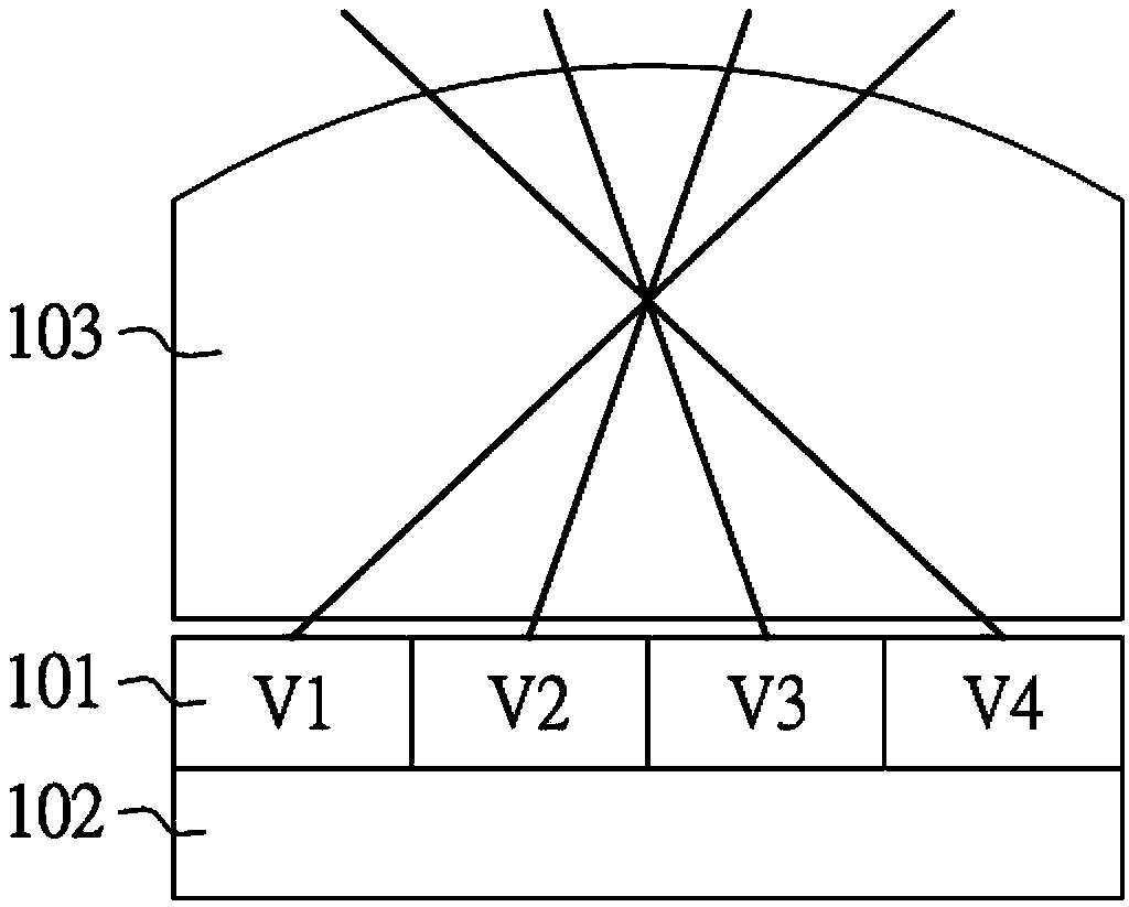
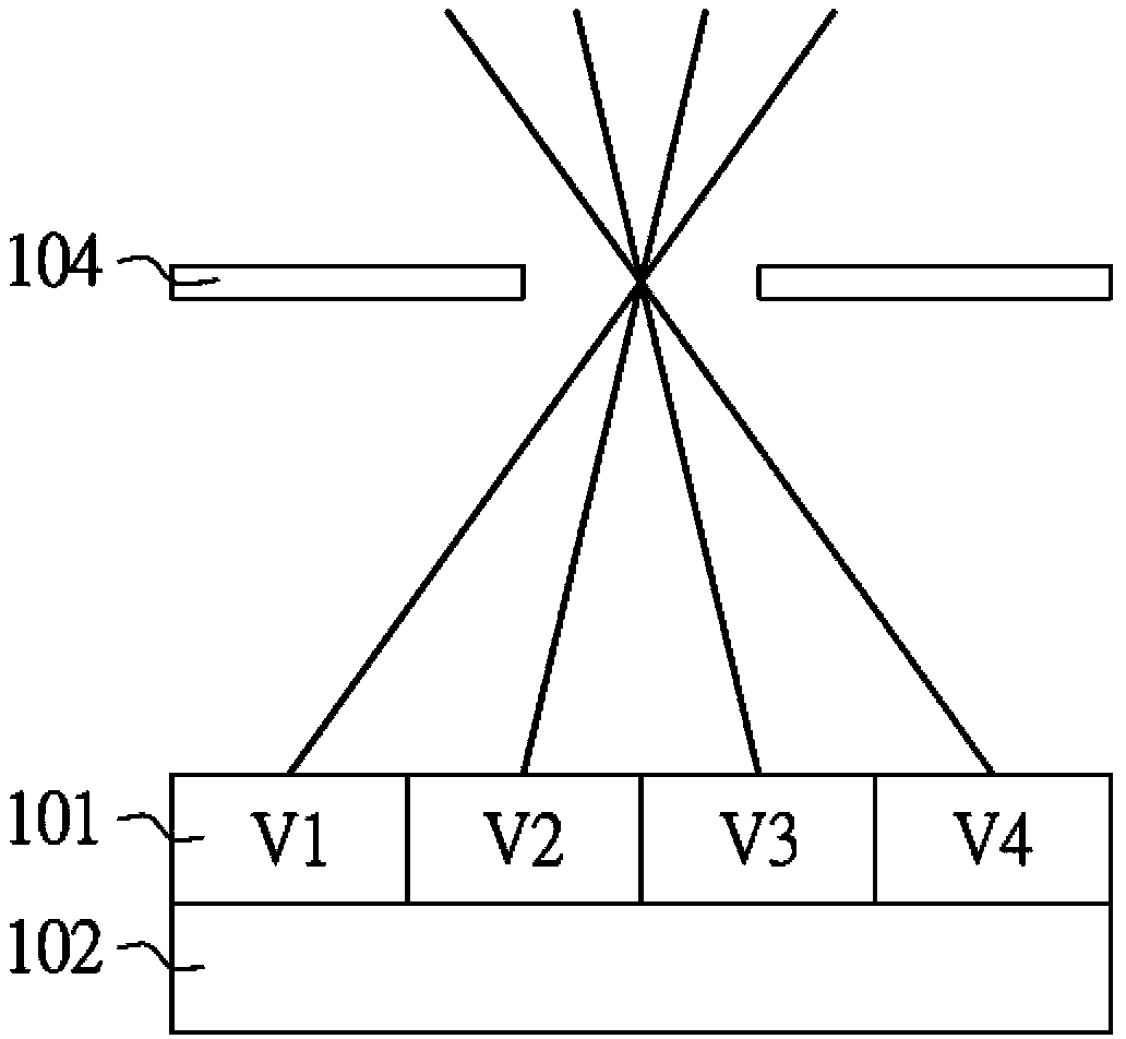
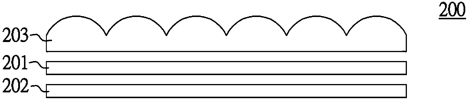
[0030] Please refer to Figure 2A and Figure 2B , respectively depicting a schematic diagram of an image layered combination structure 200 according to an embodiment of the present invention. The image layered combination structure 200 includes a plurality of image information layers 201 , 202 and an optical element layer 203 or 204 . These image information layers 201, 202 are arranged on top of each other or adjacent to each other to form an image. For example, two or more image information layers are used to form a two-dimensional image or a three-dimensional image, and then displayed in a superimposed manner. image.
[0031] The optical element layer 203 or 204 and the image information layer 201, 202 are disposed adjacent to each other up and down. The optical element layer is, for example, an optical element with one-dimensional parallax or two-dimensional parallax. The optical element with one-dimensional parallax is, for example, a lenticular lens or a grating or b...
no. 2 example
[0037] Please refer to Figure 3A and Figure 3B , respectively depicting a schematic diagram of the image layered combination structure 210 according to an embodiment of the present invention. The image layered combination structure 210 includes a plurality of image information layers 201 , 202 , an optical element layer 203 and a light source 205 . These image information layers 201, 202 are arranged on top of each other or adjacent to each other to form an image. For example, two or more image information layers are used to form a two-dimensional image or a three-dimensional image, and then displayed in a superimposed manner. image. In addition, the optical element layer 203 or 204 and the image information layer 201, 202 are disposed adjacent to each other up and down.
[0038] The layered combination of the image information layers 201 and 202 , the color separation mode of the color space, and the type of the optical element layer 203 or 204 have been introduced in de...
no. 3 example
[0042] Please refer to Figure 4A and Figure 4B , respectively depicting a schematic diagram of the image layered combination structure 220 according to an embodiment of the present invention. The image layered combination structure 220 includes a plurality of image information layers 201 , 202 , an optical element layer 203 or 204 and a light source 205 . These image information layers 201, 202 are arranged on top of each other or adjacent to each other to form an image. For example, two or more image information layers are used to form a two-dimensional image or a three-dimensional image, and then displayed in a superimposed manner. image. In addition, the optical element layer 203 or 204 and the image information layer 201, 202 are disposed adjacent to each other up and down.
[0043] The layered combination of the image information layers 201 and 202 , the color separation mode of the color space, and the type of the optical element layer 203 have been introduced in th...
PUM
 Abstract
Description
Claims
Application Information
 - R&D
- Intellectual Property
- Life Sciences
- Materials
- Tech Scout
- Unparalleled Data Quality
- Higher Quality Content
- 60% Fewer Hallucinations
Browse by: Latest US Patents, China's latest patents, Technical Efficacy Thesaurus, Application Domain, Technology Topic, Popular Technical Reports.
© 2025 PatSnap. All rights reserved.Legal|Privacy policy|Modern Slavery Act Transparency Statement|Sitemap|About US| Contact US: help@patsnap.com