

Image processing method and device applied to tiled display equipment
A technology of splicing display and images, applied in static indicators, cathode ray tube indicators, instruments, etc., can solve problems such as character loss, and achieve the effect of good display effect and good character display effect.
- Summary
- Abstract
- Description
- Claims
- Application Information
AI Technical Summary
Problems solved by technology
Method used
Image

Examples
Embodiment 1
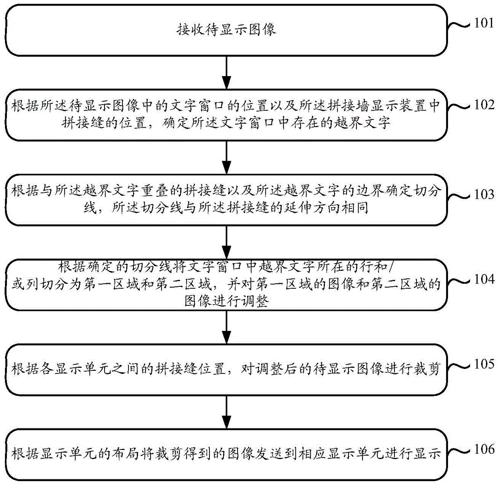
[0074] Such as figure 2 As shown, it is a flow chart of the steps of an image display method provided in Embodiment 1 of the present invention. The method is mainly applied to the process of displaying images on a spliced display device. The spliced display device generally includes a plurality of display units. And there is a seam between adjacent display units due to the frame of the display unit.
[0075] The image display method includes:
[0076] Receive the image to be displayed;
[0077] When it is determined that a character is included in the preset segmented area, the position of the character is moved so that the character is not included in the preset segmented area.
[0078] When the preset segmented area in the splicing display device is a splicing seam of the splicing display device, the above method specifically includes the following steps:
[0079] Step 101: Receive an image to be displayed, where the image to be displayed includes a character window....
Embodiment 2
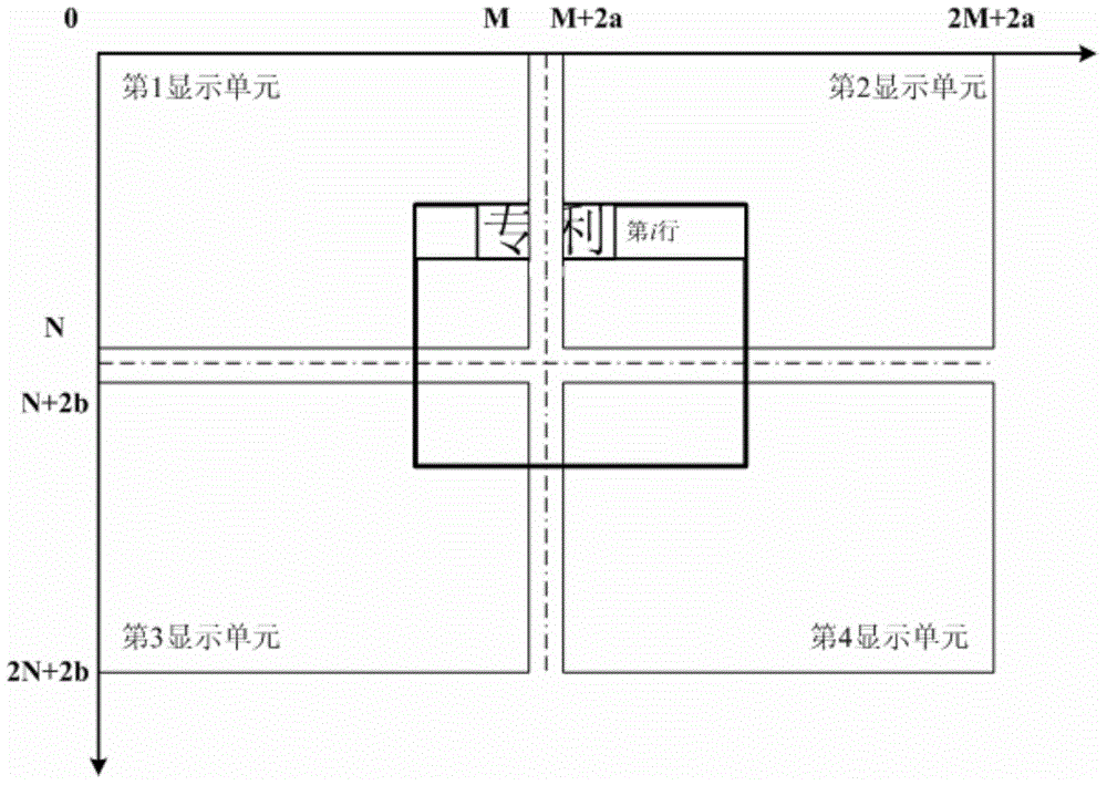
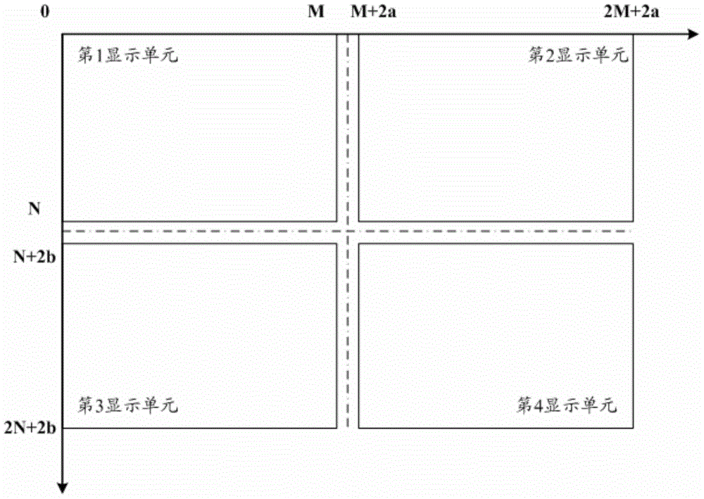
[0096] as image 3 The splicing display device composed of 2×2 display units is shown as an example, where the display unit in the upper left corner is the first display unit, the display unit in the upper right corner is the second display unit, and the display unit in the lower left corner is the third display unit unit, the display unit in the lower right corner is the fourth display unit. The resolution of each display unit is M×N, the horizontal resolution corresponding to the vertical seam is 2a, the vertical resolution is 2N+2b, the horizontal resolution corresponding to the horizontal seam is 2M+2a, and the vertical resolution is 2b; According to the distribution position and combination of the 4 display units, it can be obtained that the resolution of the spliced display device composed of the 2×2 display units is (2M+2a)×(2N+2b), and the resolution of the spliced display device includes Displays the resolution of cells and seams.
[0097] After the spliced di...
example 1
[0103] If it is detected that there is a character in the vertical seam in the character line of the i-th row, then part or all of the character and the vertical seam (coordinates are (M, 0), (M+2a, 0) , (M, 2N+2b) and (M+2a, 2N+2b)) overlap, and the characters overlap with the projection of the central axis of the seam. The row where the character is located spans the first display unit and the second display unit.
[0104] Get the left boundary coordinate Xi of the character in the horizontal direction left and the right boundary coordinate Xi right ;Specifically, when the central axis of the stitching seam overlapping with the character is at the same distance from the left and right borders of the character, the extension line of any border in the two borders is determined as the segmentation Wire.
[0105] (1) As shown in Figure 5(a), when |Xi left -(M+a)|rightt When -(M+a)|, the left boundary coordinate Xi of the character "please" left The extension line where is d...
PUM
 Abstract
Description
Claims
Application Information