

GPU-based video displaying method for rotary antenna radar
A technology of video display and rotating antenna, applied in radio wave measurement systems, instruments, etc., can solve the problems of backward scanning conversion method, poor display effect, high cost of hardware board development, upgrade and maintenance, and achieve good display effect and high The effect of flexibility, improved reliability and ease of maintenance
- Summary
- Abstract
- Description
- Claims
- Application Information
AI Technical Summary
Problems solved by technology
Method used
Image

Examples
Embodiment Construction
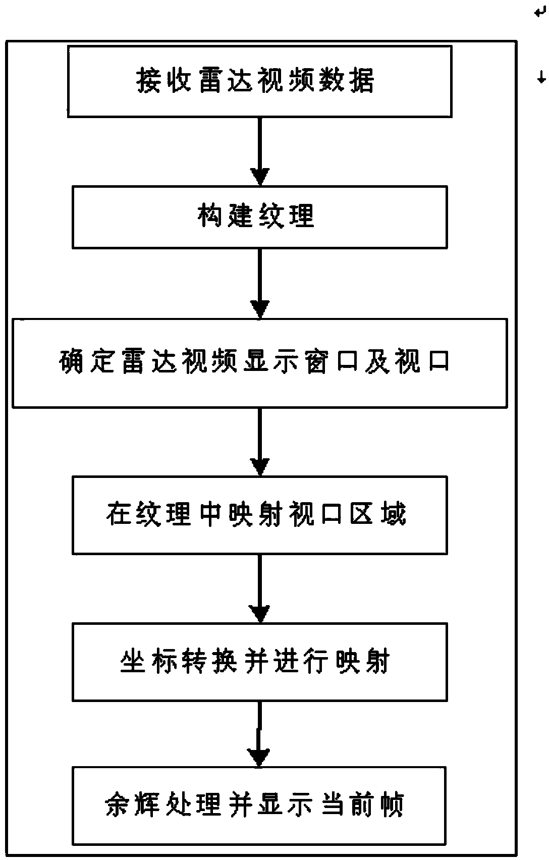
[0028] refer to figure 1 , illustrate a kind of rotating antenna radar of the present invention based on the video display method of GPU (Graphic Processing Unit), it comprises the following steps:
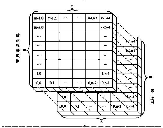
[0029] Step 1, receiving radar video data: receive continuous radar video data according to azimuth, and extract the current azimuth value th and the rotation direction of the radar antenna; wherein, the radar video data is the unit data of m azimuth dimensions and n distance dimensions.
[0030] Step 2, constructing textures: constructing an m×n-dimensional first texture and an m×n-dimensional second texture according to unit data, the first texture storing unit data.
[0031] Set the size and parameters of the first texture and the second texture, specifically: in order to make the texture coordinates correspond to the m×n-dimensional unit data positions one-to-one, the texture type of the first texture needs to be set to rectangular texture, and the texture format is set to It...
PUM
 Abstract
Description
Claims
Application Information