Electric connection device and connector

A technology for electrical connection and equipment, applied in the field of electrical connection equipment for charging, can solve problems such as arranging slots, and achieve the effect of improving reliability and simplifying the electrical connection process

Active Publication Date: 2014-08-13
XIAMEN YUNDUO NETWORK TECH
View PDF8 Cites 0 Cited by
  • Summary
  • Abstract
  • Description
  • Claims
  • Application Information

AI Technical Summary

Problems solved by technology

However, for some devices with special shapes, such as wearable devices arranged on shoes, cloth

Method used


Image

  • Electric connection device and connector
  • Electric connection device and connector
  • Electric connection device and connector

Examples


Example Embodiment

[0023] Hereinafter, exemplary embodiments of the present disclosure will be described in more detail with reference to the accompanying drawings. Although exemplary embodiments of the present disclosure are shown in the drawings, it should be understood that the present disclosure can be implemented in various forms and should not be limited by the embodiments set forth herein. On the contrary, these embodiments are provided to enable a more thorough understanding of the present disclosure and to fully convey the scope of the present disclosure to those skilled in the art.
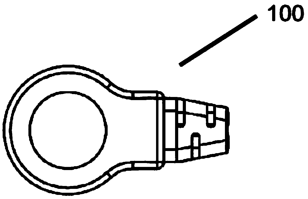
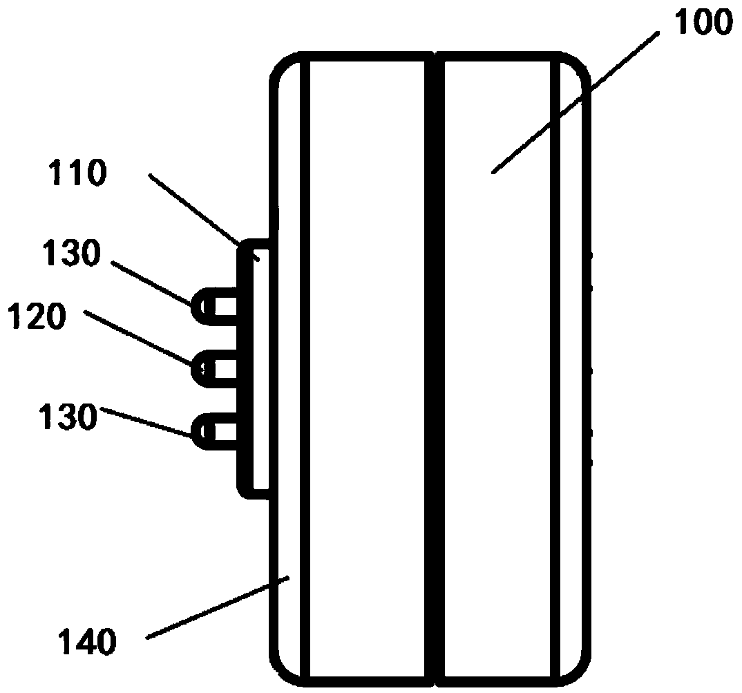
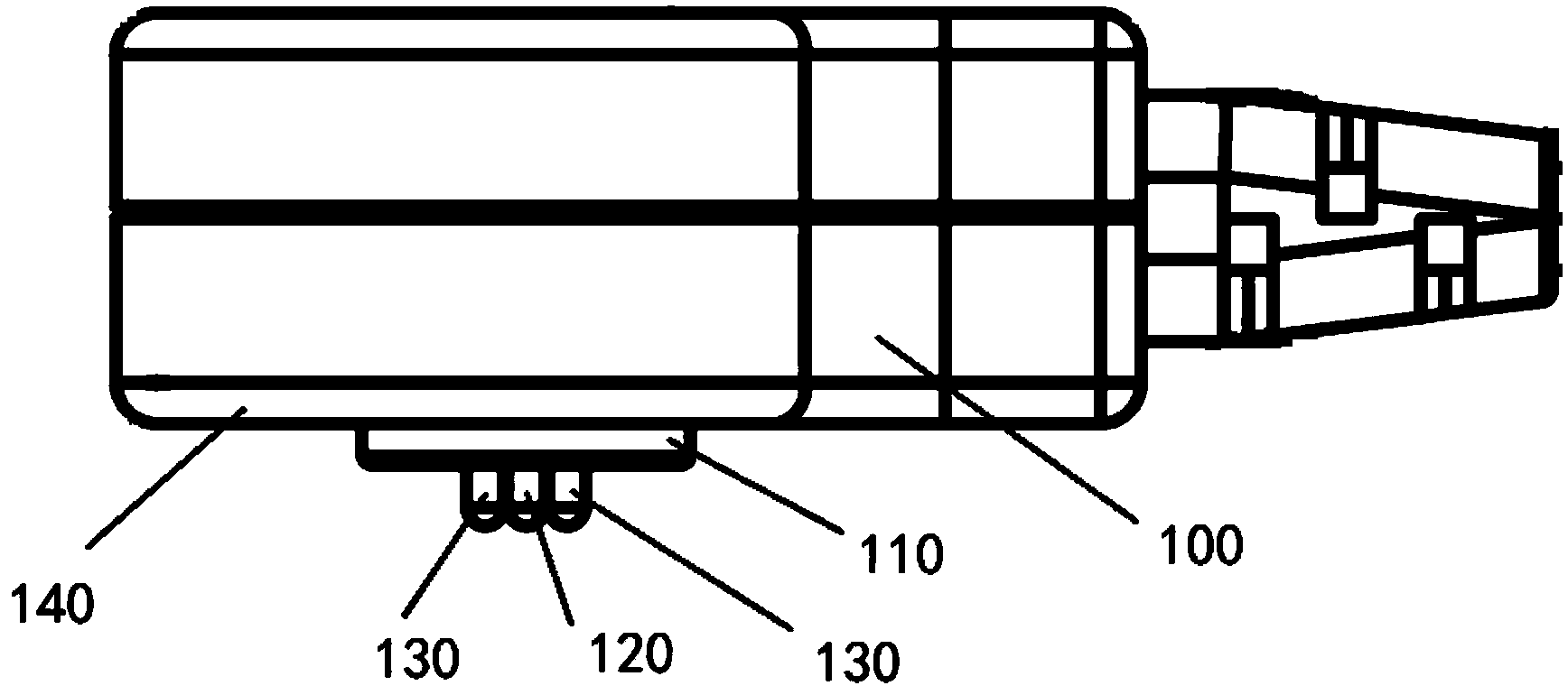
[0024] Figure 1-4 The front view, side view, top view and back view of the electrical connection joint 100 according to an embodiment of the present invention are shown. Such as Figure 1-4 As shown, the electrical connection connector 100 includes a base 110 on one side of the connector 100. The base 110 is substantially cylindrical, and a first terminal 120 is arranged at the center of the cylinder. Th...


PUM


Abstract

The invention discloses an electric connection connector. The connector comprises a base, a first connecting column, one or more second connecting column and a magnetic component, wherein the first connecting column is located in the center of the base, the second connecting columns are distributed on the circumference, away from the center of the base by a preset distance, of the base, and the magnetic components are located behind the base. The invention further discloses a second electric connection connector used in pairs with the electric connection connector and an electric connection device comprising the two electric connection connectors.

Description

technical field [0001] The invention relates to the field of electrical connection interfaces, in particular to an electrical connection device and method for charging. Background technique [0002] With the rapid development of the mobile Internet, many mobile devices appear, and these mobile devices need to use external power sources to charge batteries in the devices. A common charging connector includes a socket in the mobile device and a plug on the cable. In use, the mobile device is charged by inserting the plug into the slot of the mobile device. Since the slot needs a certain depth, for some mobile devices with a relatively standard volume, the slot can be included in the device relatively easily. However, for some devices with special shapes, such as wearable devices arranged on shoes, clothes, etc., it is difficult to arrange slots in these devices, but these devices need to be charged. Therefore, there is a need for an electrical connection scheme suitable for...

Claims


Application Information

Patent Timeline
IPC IPC(8): H01R13/631
Inventor 林海
Owner XIAMEN YUNDUO NETWORK TECH
Why Eureka
Try Eureka