[0035] Hereinafter, preferred embodiments of the present disclosure will be described in detail with reference to the accompanying drawings. Before the description, it is to be understood that the terms used in the specification and the appended claims should not be construed as limited to their ordinary and dictionary meanings, but should be construed based on the principle that the inventor is permitted to define the terms appropriately for the best interpretation. Meanings and concepts corresponding to technical aspects of the present disclosure. Accordingly, the descriptions presented herein are only preferred examples for illustrative purposes only and are not intended to limit the scope of the disclosure, it being understood that other equivalents may be made without departing from the scope of the disclosure and modification.
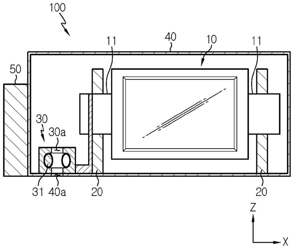
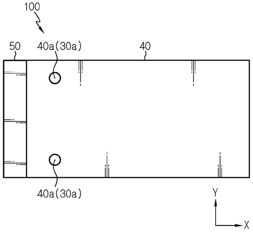
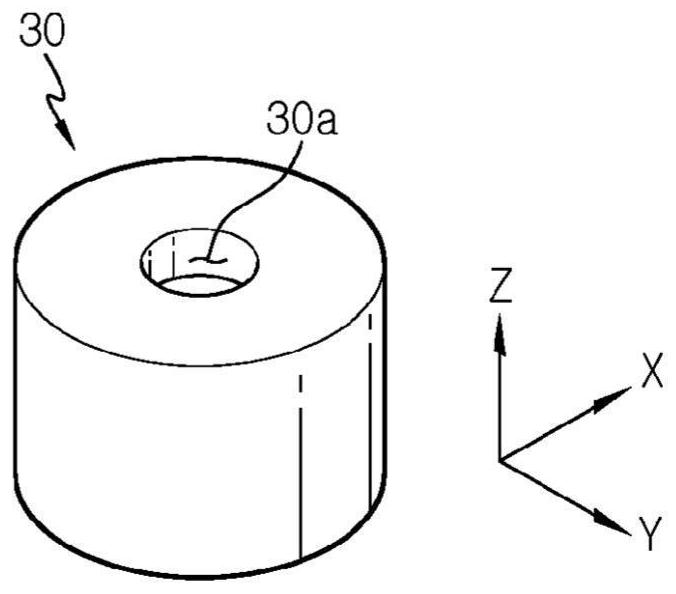
[0036] refer to Figure 1 to Figure 3 , the battery module 100 according to an embodiment of the present disclosure will be described.
[0037] The battery module 100 includes a plurality of battery cells 10 , a pair of vent terminals 30 and a module case 40 . The battery module 100 may also include a bus bar frame 20 for electrical connection between the plurality of battery cells 10 . In addition, the battery module 100 may further include the end plate 50 according to the shape of the module case 40 .
[0038] For example, a pouch-type battery cell may be used as the battery cells 10, and in this case, each battery cell 10 includes a pair of electrode leads 11 having opposite polarities. A plurality of battery cells 10 are stacked facing each other to form one cell stack. The plurality of battery cells 10 may be connected to each other in series, in parallel, or a combination of both.
[0039] The bus bar frame 20 may be provided only on one side in the longitudinal direction (direction parallel to the X axis) of the cell stack, or may be in the same direction or opposite depending on whether a pair of electrode leads 11 provided in the battery cell 10 The direction is drawn out to be provided on both one side and the other side in the longitudinal direction of the cell stack. Although not specifically shown, the bus bar frame 20 includes at least one bus bar. The bus bars are used to connect the electrode leads 11 of adjacent battery cells.
[0040] In the battery module 100, the bus bar frame 20 may be omitted. That is, the electrical connection between the plurality of battery cells 10 does not necessarily have to be performed by the bus bar frame 20 , but may be performed by at least one bus bar, or may be performed by directly contacting the electrode leads 11 of the adjacent battery cells 10 Without using a medium for electrical connection.
[0041] The vent terminal 30 is electrically connected to the cell stack, and is located on one surface of the module case 40 . The vent terminal 30 may be located, for example, on the bottom surface of the module case 40 . The exhaust hole terminal 30 includes a terminal hole 30 a that communicates with the module hole 40 a through one surface of the module case 40 . A pair of vent terminals 30 are provided. One of the pair of vent terminals 30 is connected to the first electrode of the cell stack, and the remaining one is connected to the second electrode of the cell stack. The first electrode and the second electrode are electrodes having opposite polarities. For example, one vent terminal of a pair of vent terminals 30 may be provided by being coupled to one of the outermost battery cells 10 positioned on the outermost one in the stacking direction (direction parallel to the Y axis) on the outermost battery cell 10 An electrode lead 11 having a first polarity (hereinafter, referred to as a first electrode lead) among the electrode leads 11 is electrically connected to the cell stack. Similarly, the remaining one of the pair of vent terminals 30 may be provided by being coupled to a pair of electrodes provided in the outermost battery cell 10 located on the other outermost side in the stacking direction of the battery stack An electrode lead 11 having a second polarity opposite to the first polarity among the leads 11 (hereinafter, referred to as a second electrode lead) is electrically connected to the cell stack. Alternatively, the vent terminal 30 may be electrically connected to the cell stack through a bus bar (not shown) provided in the bus bar frame 20 .
[0042] A pair of vent terminals 30 serve as positive and negative terminals of each battery module 100 and serve for discharging gas to the module case when gas is generated due to the venting of the battery cells 10 within the module case 40 path outside of body 40 .
[0043]The vent terminal 30 may be formed of a conductive metal material, and may have a hollow cylindrical shape of a terminal hole 30 a formed in a height direction (direction parallel to the Z axis). The exhaust hole terminal 30 may include a conductive elastic member 31 fixed to the inner peripheral surface of the terminal hole 30a. The conductive elastic member 31 may have an annular shape having a through hole in the central portion, and for example, a commonly used contact spring may be used as the conductive elastic member 31 . When an external terminal having a hollow tubular shape is inserted into the terminal hole 30a to electrically connect the plurality of battery modules 100, the conductive elastic member 31 presses and fixes the outer peripheral surface of the inserted terminal.
[0044] The cell stack, the bus bar frame 20 and the pair of vent terminals 30 are accommodated in the module case 40 . As described above, the module case 40 includes a pair of module holes 40a formed on both sides in the width direction (direction parallel to the Y axis) of the bottom surface. The pair of module holes 40a are formed at positions corresponding to the terminal holes 30a, so that the inner space and the outer space of the module case 40 communicate through the terminal holes 30a and the module holes 40a.
[0045] Next, refer to Figure 4 to Figure 9 A battery pack according to an embodiment of the present disclosure is described.
[0046] A battery pack according to an embodiment of the present disclosure includes a module assembly including a plurality of battery modules 100 , a battery pack case 200 , a fluid channel bracket 300 and a plurality of vent studs 400 according to an embodiment of the present disclosure.
[0047] The module assembly, fluid channel brackets 300 and vent studs 400 are housed in the battery pack housing 200 . The pack case 200 has at least one pack hole 200a through which exhaust gas is discharged from the battery module 100 to the outside. Although in Figure 4 The battery hole 200a is formed only in the side surface (surface parallel to the X-Z plane) of the battery case 200, but the position of the battery hole 200a is not limited thereto.
[0048] The fluid channel holder 300 extends in the width direction of the battery pack (direction parallel to the Y axis), and includes an empty inner space (ie, exhaust gas fluid channel P) through which exhaust gas can flow. The exhaust gas fluid passage P passes through both ends of the fluid passage holder 300 in the longitudinal direction.
[0049] The fluid passage holder 300 serves as a holder on which the plurality of battery modules 100 are mounted, and serves as a passage through which exhaust gas discharged from the battery modules 100 passes. The fluid passage holder 300 has a plurality of holder holes 300a formed in the top surface in the longitudinal direction to serve as passages through which the exhaust gas flows. Each of the plurality of bracket holes 300a is in communication with the exhaust gas fluid passage P. As shown in FIG. The plurality of holder holes 300 a are formed at positions corresponding to the plurality of module holes 40 a formed in the bottom surfaces of the plurality of battery modules 100 mounted on the fluid channel holder 300 , respectively.
[0050] refer to Image 6 , the vent stud 400 is fixed on the fluid channel bracket 300 , and is fixedly inserted into the module hole 40 a and the terminal hole 30 a to be electrically connected to the vent terminal 30 . Thus, the vent studs 400 are electrically connected to the cell stack.
[0051] The vent stud 400 includes a base portion 410a coupled to the top surface of the fluid channel bracket 300 and an insertion portion 420a fixedly inserted into the module hole 40a and the terminal hole 30a. The vent stud 400 has a stud hole 400a passing through the base portion 410 and the central portion of the insertion portion 420a in the height direction (direction parallel to the Z axis). The stud hole 400a communicates with the module hole 40a and the terminal hole 30a. Further, the stud hole 400a communicates with the bracket hole 300a. That is, the plurality of vent hole studs 400 are located at positions corresponding to the plurality of bracket holes 300a, respectively.
[0052] Among the plurality of vent studs 400 , the vent stud 400 inserted into the module hole 40 a formed in any one of the battery modules 100 of a pair of adjacent battery modules 100 and inserted into the opposite battery module 100 formed in the pair The vent studs 400 in the module holes 40a in the other battery module 100 of the adjacent battery modules 100 are electrically connected to each other. For example, a connector 500 having a metal strip shape may be used to electrically connect a pair of adjacent vent studs 400 . The connector 500 may be integrally formed with the pair of vent studs 400 . The reason why a pair of adjacent vent studs 400 are electrically connected to each other is to connect adjacent battery modules 100 in series. Among the plurality of vent studs 400 spaced apart from each other in the longitudinal direction (direction parallel to the Y direction) of the fluid channel holder 300 , a pair of outermost vent holes 400 on the two outermost sides serve as batteries, respectively The positive and negative electrode terminals of the group, and the remaining vent studs 400 are used as connecting bars for connecting the plurality of battery modules 100 .
[0053] refer to Figure 8 , the insulating member 600 may be located between the base 410 of the vent stud 400 and the top surface of the fluid channel bracket 300 . This is to prevent current from flowing through the plurality of vent studs 400 formed of a conductive metal material when the fluid channel holder 300 is formed of a metal material to ensure rigidity. The insulating member 600 may, for example, be coated on the surface of the fluid channel holder 300 formed of a conductive material. When the fluid channel holder 300 is formed of a non-conductive material, the insulating member 600 may be omitted.
[0054] refer to Figure 9 , one end and/or the other end of the fluid channel holder 300 in the longitudinal direction may be tightly attached to the side wall of the battery case 200 in which the battery hole 200a is formed, and may be connected with the battery hole 200a. 200a connected. Therefore, when the exhaust gas fluid channels P formed in the fluid channel holder 300 and the battery pack hole 200a are directly communicated with each other, the high-temperature exhaust gas can be made without contacting the battery modules other than the battery module where abnormality occurs and the gas is exhausted. It can be quickly discharged to the outside under the circumstances, thereby improving the safety of the battery pack.
[0055] The vehicle according to the embodiment of the present disclosure includes the battery module 100 and/or the battery pack according to the embodiment of the present disclosure as described above as a power source.
[0056] As described above, since the battery module 100 according to the embodiment of the present disclosure includes the vent terminal 30, and the battery pack according to the embodiment of the present disclosure includes the stud holes 400a, a plurality of battery modules 100 for manufacturing the battery pack The installation and electrical connection of the exhaust gas, as well as the formation of the fluid passage for discharging the exhaust gas, can be performed simultaneously. Furthermore, in the battery module 100 according to the embodiment of the present disclosure, since the vent terminal 30 serving as the module terminal is located in the direction substantially perpendicular to the direction in which the electrode lead 11 is drawn out, during the venting of the battery cell 10 The risk of events caused by high temperature exhaust gases can be minimized. That is, since the exhaust port terminal 30 of the present disclosure is used as the high potential terminal of the battery module 100 and the high potential terminal on which heat can be concentrated is not located in the direction in which the high temperature exhaust gas is discharged, it is possible to improve the Safety in use of the battery module 100 .
[0057] The present disclosure has been described in detail. It should be understood, however, that the detailed description and specific examples, while indicating preferred embodiments of the present disclosure, are given by way of illustration only, for various changes and modifications within the scope of the present disclosure as defined by the appended claims It will become apparent to those skilled in the art from this detailed description.