A high-efficiency integrated dual-rotor bidirectional generator device

A dual-rotor, generator technology, applied in electromechanical devices, electrical components, electric components, etc., can solve the problems of difficult to start, difficult to start, low structural strength, etc., to avoid inertial impact, improve service life, and improve power generation quality. Effect

Inactive Publication Date: 2016-11-02
SOUTHEAST UNIV
View PDF8 Cites 0 Cited by
  • Summary
  • Abstract
  • Description
  • Claims
  • Application Information

AI Technical Summary

Problems solved by technology

However, the device is more suitable for vertical arrangement, and the horizontal arrangement will have low structural strength, and it is difficult to meet the stable operation under a large force state.
[0005] In the patent No. ZL200910264407.4, it is disclosed that the drive conversion device is composed of a shunt transmission gear shaft, a reverse ring gear, a steering shaft, etc., and in the patent No. ZL201210334291.9, a planetary gearbox is used as a drive conversion device to realize double rotation. However, the starting torque of the generator is relatively large, and it is not easy to start
[0006] In the patent No. ZL02235745.9, it is disclosed that the inner shaft is fixedly connected with the inner rotor, and a set of impellers that rotate clockwise after being stressed by the torsion angle are installed; The rotors are fixedly connected, and at the same time, a set of impellers that rotate counterclockwise after being stressed by the torsion angle is installed, so as to realize the double rotor reversal. resistance, so the efficiency of the device will be lower
[0007] Combining the dual-rotor generators that have been developed so far, although they are different in terms of drive conversion devices, they have a common feature, that is, the fundamental principle is to use two shafts, and the two ends of each shaft are respectively connected to a The rotor is fixedly connected to an impeller, so the rotation of the dual rotors will change with the rotation of the impeller. This will not only affect the quality of power generation, but also cause the generator to start with high resistance and difficult to start, and its life is low. Therefore, the existing dual-rotor generators are only suitable for some specific occasions, such as in one-way fluid with stable flow velocity, but not for two-way power generation with unstable flow direction.

Method used


Image

  • A high-efficiency integrated dual-rotor bidirectional generator device
  • A high-efficiency integrated dual-rotor bidirectional generator device
  • A high-efficiency integrated dual-rotor bidirectional generator device

Examples


Embodiment Construction

[0031] The present invention will be further described below in conjunction with the accompanying drawings.

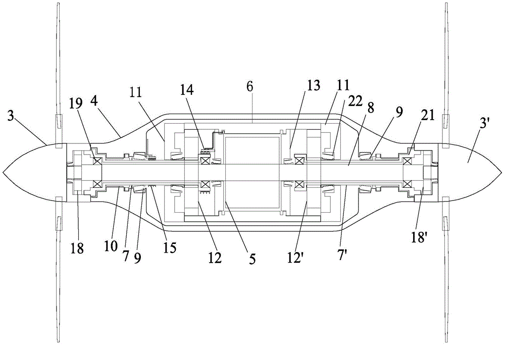
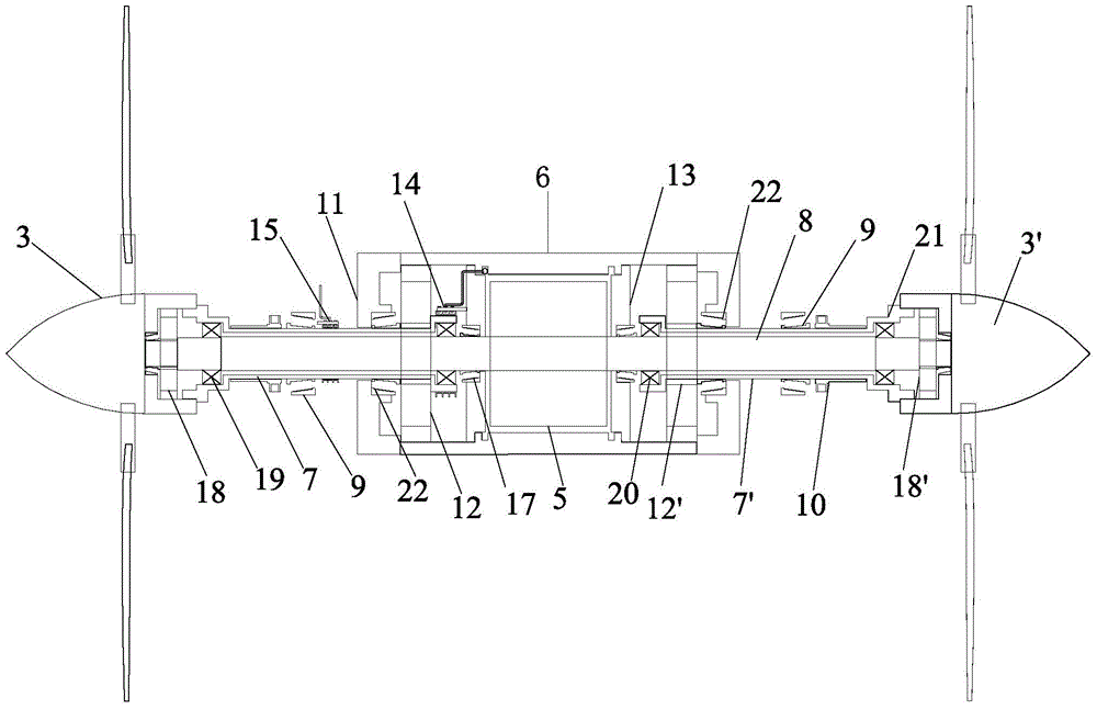
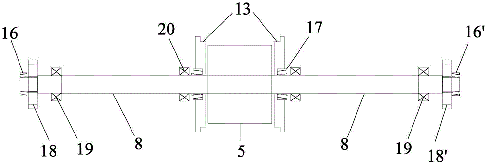
[0032] like Figure 1 to Figure 4As shown, a high-efficiency integrated dual-rotor bidirectional generator device includes a casing 4, a first impeller 3 and a second impeller 3' arranged at both ends of the casing 4, and an inner rotor driving device and an outer rotor driving device inside the casing 4. device; the inner rotor driving device includes an inner shaft 8, an inner rotor 5 set in the middle of the inner shaft 8, a first one-way gear 18 and a second one-way gear 18' set at both ends of the inner shaft 8, the first A first one-way gear 18 and a second one-way gear 18' are respectively provided with a first thrust bearing 16 and a second thrust bearing 16' on the outside, and the outer teeth 2 of the first one-way gear 18 and the second one-way gear 18' They are detachably fixedly connected with the first impeller 3 and the second impeller 3'; the outer rot...


PUM


Abstract

The invention discloses an efficient and integrated double-rotor bidirectional power generator device. The device comprises a shell, a first impeller, a second impeller, an inner rotor drive device and an outer rotor drive device, wherein the first impeller and the second impeller are arranged at the two ends of the shell respectively, and the inner rotor drive device and the outer rotor drive device are arranged in the shell. The inner rotor drive device comprises an inner shaft, an inner rotor arranged in the middle of the inner shaft, a first one-way gear and a second one-way gear, wherein the first one-way gear and the second one-way gear are arranged at the two ends of the inner shaft respectively. The outer rotor drive device comprises an outer rotor, a third one-way gear, a fourth one-way gear, a first outer shaft and a second outer shaft, wherein the first outer shaft and the second outer shaft are arranged on the two sides of the inner rotor respectively. The rotation direction of the inner rotor and the rotation direction of the outer rotor keep unchanged all the time, and accordingly power generation quality can be improved, inertia impact generated when the rotation directions of the impellers change between the impellers and the rotors can be effectively avoided, the service life of the power generator is prolonged, and additionally, the problem that the power generator is difficult to start can be solved due to the one-way gears.

Description

technical field [0001] The invention discloses a power generation device, in particular to a high-efficiency integrated double-rotor bidirectional generator device. Background technique [0002] Traditionally used generators are mainly composed of a stator and a rotor. The stator is fixed, and the rotor rotates to generate electricity. In recent years, some people have proposed a new type of generator structure, that is, the stator of the generator is removed, and instead it contains two rotors, and the two rotors can realize simultaneous reverse relative rotation by driving the conversion device. [0003] Although some people have designed generators that can meet these special requirements, and the general power generation principles of these generators are similar, but the key system for realizing the drive conversion device with dual rotors that can rotate in reverse at the same time is different. various. [0004] Wang Jingjing, Ye Sijin, Zheng Weigang. Design of a ne...

Claims


Application Information

Patent Timeline
Patent Type & Authority Patents(China)
IPC IPC(8): H02K16/00H02K7/18H02K7/116
Inventor 吕进
Owner SOUTHEAST UNIV
Why Eureka
Try Eureka