
Edge folding die for U-shaped steel plate

A steel plate and mold technology, which is applied in the field of folding molds for U-shaped steel plates, can solve the problems of inconvenience, low processing efficiency, time-consuming and laborious, etc.

Inactive Publication Date: 2014-08-20
昆山电子羽电业制品有限公司
View PDF7 Cites 10 Cited by
  • Summary
  • Abstract
  • Description
  • Claims
  • Application Information

AI Technical Summary

Problems solved by technology

In the prior art, for the hemming of U-shaped sheet metal workpieces, since the molds used can only realize one-sided hemming, this type of sheet metal workpieces have to be hemmed twice, which will result in low processing efficiency
In addition, the processed plate workpiece is often stuck in the mold after being folded and formed, requiring manual tools to pry it, which is time-consuming, laborious, and inconvenient

Method used


Image

  • Edge folding die for U-shaped steel plate
  • Edge folding die for U-shaped steel plate

Examples


Embodiment Construction

[0012] The technical solutions of the present invention will be further described below in conjunction with the accompanying drawings and through specific implementation methods.

[0013] In describing the present invention, it should be understood that the terms "longitudinal", "transverse", "upper", "lower", "front", "rear", "left", "right", "vertical", The orientation or positional relationship indicated by "horizontal", "top", "bottom", "inner", "outer", etc. are based on the orientation or positional relationship shown in the drawings, and are only for the convenience of describing the present invention and simplifying the description, rather than Nothing indicating or implying that a referenced device or element must have a particular orientation, be constructed, and operate in a particular orientation should therefore not be construed as limiting the invention.

[0014] In the description of this specification, descriptions referring to the terms "one embodiment", "some...


PUM


Abstract

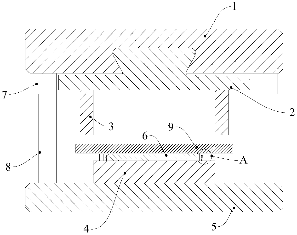
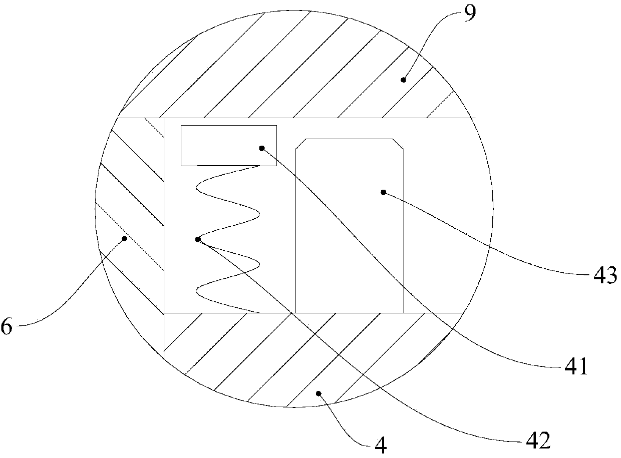
The invention discloses an edge folding die for a U-shaped steel plate. According to the edge folding die, an edge folding male die is arranged on an upper die plate, a stamping table, a spring and an ejecting block are arranged on a lower die fixing plate, the stamping table is used for containing the steel plate, the ejecting block is connected with the spring, and an electromagnet is arranged inside the stamping table. The steel plate with the edge to be folded is placed on the stamping table, the electromagnet is powered on to generate magnetic force, the steel plate is attacked and attached to the stamping table, the edge folding lower die moves downwards to stamp the workpiece to complete edge folding, and the spring is in the compression state at the moment; when folding of the edge of the steel plate is completed and the edge folding male die moves upwards, an electromagnet unit is powered off, the magnetic force disappears, the steel plate is jacked away from the stamping table by the ejecting block driven by the spring, and discharging is completed automatically.

Description

technical field [0001] The invention relates to the technical field of molds, in particular to a folding mold for U-shaped steel plates. Background technique [0002] Workpieces such as plates (steel plates) generally need to be folded with a folding die during punch processing. For the hemming forming of U-shaped plate workpieces in the prior art, since the molds used can only realize one-sided hemming, the plate workpieces of this type have to be hemmed twice, which will result in low processing efficiency. In addition, the processed plate workpiece is often stuck in the mold after being folded and formed, which requires manual tools to pry it, which is time-consuming, laborious and inconvenient. Contents of the invention [0003] In view of this, the present invention provides a hemming mold for U-shaped steel plates, which can realize double-sided hemming at one time, and the hemming mold can automatically separate the processed workpiece from the mold, which is more ...

Claims


Application Information

Patent Timeline
Patent Type & Authority Applications(China)
IPC IPC(8): B21D37/10B21D19/00B21D45/04
Inventor 尹纯军
Owner 昆山电子羽电业制品有限公司
Learn More