Suspension Device of Electromagnetic Track Brake for Light Rail Vehicles

A technology of rail brakes and suspension devices, which is applied in the directions of brakes where braking elements interact with rails, railway braking systems, transportation and packaging, etc. Aluminium paste service life and other issues, to achieve the effect of reducing equipment maintenance workload, avoiding safety accidents, and reducing use costs

Active Publication Date: 2016-04-20
华伍轨道交通装备(上海)有限责任公司
View PDF5 Cites 3 Cited by
  • Summary
  • Abstract
  • Description
  • Claims
  • Application Information

AI Technical Summary

Problems solved by technology

[0003] The suspension device that the electromagnetic track brake that is applied to the low-floor light rail vehicle adopts at present mainly is made of adjusting screw mandrel, suspension spring, dust cover and elastic nut etc., but but existing suspension device has the problem of two aspects: the one is The length of the rubber dust cover in the middle of the adjustment screw is small and there are no fixing devices at both ends of the dust cover to position it. The dust cover cannot completely cover the thread in the middle of the adjustment screw, and the stiffness of the dust cover itself is small. After a certain period of use, the rubber material fatigues and ages, and the dust cover will deform and shrink under the action of its own gravity, resulting in a longer adjustment screw thread being exposed to the external environment, thus making the anti-adhesion coating on the adjustment screw thread part Aluminum paste is easy to mix with water vapor and dust, which greatly shortens the service life of aluminum paste and increases the maintenance workload and use cost of electromagnetic track brake related equipment; It is easy to loosen under the vibration and impact caused by unevenness, and it is easy to loosen down under the gravity of the electromagnet, resulting in a smaller gap between the electromagnet and the top of the track in the non-working state. In severe cases, it may even contact or collide with the track. security incident

Method used


Image

  • Suspension Device of Electromagnetic Track Brake for Light Rail Vehicles
  • Suspension Device of Electromagnetic Track Brake for Light Rail Vehicles

Examples


Embodiment 1)

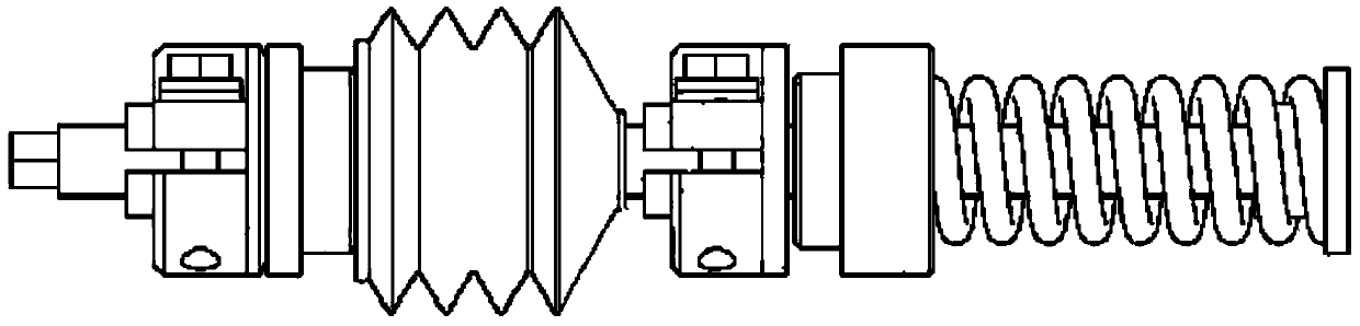
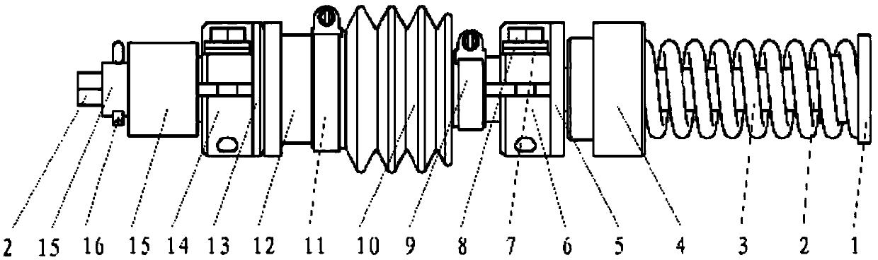
[0013] See figure 2 The suspension device of the light rail vehicle electromagnetic track brake of the present embodiment comprises an end cover 1, an adjusting screw mandrel 2, a suspension spring 3, a spring tray 4, a flat washer 5, an upper elastic nut 6, a dish washer 7, a bolt 8, Upper clamp 9, dust cover 10, lower clamp 11, suspension tray 12, spherical gasket 13, lower elastic nut 14, locking sleeve 15 and cotter pin 16.

[0014] The end cap 1 is an integral piece made of steel. The end cap 1 is a hollow structure integrally formed by two sections of cylinders with different outer diameters, wherein the upper cylinder has a relatively larger outer diameter and a relatively shorter length. The central hole of the end cap 1 is an internally threaded cylindrical through hole.

[0015] The adjusting screw rod 2 is a strip-shaped high-strength rolled stainless steel stud, and the thread diameter of the adjusting screw rod 2 matches the threaded through hole of the end cov...


PUM


Abstract

The invention provides a suspension device of a light rail vehicle electromagnetic track brake. The suspension device comprises an end cover, an adjusting lead screw, a suspension spring, a spring tray, a flat gasket, an upper elastic nut, a plate-shaped gasket, a bolt, a dust-proof cover, a suspension tray, a spherical surface gasket and a lower elastic nut and is structurally characterized by further comprising an upper clamp hoop, a lower clamp hoop, a locking sleeve and an open pin. The upper clamp hoop and the lower clamp hoop respectively enable upper and lower ports of the dust-proof cover to be clamped and fixed on the upper elastic nut and the suspension tray. The locking sleeve is arranged under the lower elastic nut and fixes the locking sleeve on the adjusting lead screw through the open pin. Due to the fact that the upper and lower clamp hoops are added on the suspension device, the dustproof and moisture-proof performance is improved greatly, the service life of the device is prolonged, and the maintenance amount and the using cost of the device are reduced. The locking sleeve is added, so that the safety performance of the device is improved, and safety accidents can be effectively avoided.

Description

[0001] This application is a divisional application of the invention patent application with the application number 201210067955.X and the application date being March 15, 2012, and the invention name is "Electromagnetic Track Brake Suspension Device for Light Rail Vehicles". technical field [0002] The invention relates to the field of electromagnetic track brakes for rail vehicles, in particular to a suspension device for electromagnetic track brakes for low-floor light rail vehicles. Background technique [0003] The suspension device that the electromagnetic track brake that is applied to the low-floor light rail vehicle adopts at present mainly is made of adjusting screw mandrel, suspension spring, dust cover and elastic nut etc., but but existing suspension device has the problem of two aspects: the one is The length of the rubber dust cover in the middle of the adjustment screw is small and there are no fixing devices at both ends of the dust cover to position it. The...

Claims


Application Information

Patent Timeline
Patent Type & Authority Patents(China)
IPC IPC(8): B61H7/08
Inventor 姚雪荣李程吴冬华王晓东
Owner 华伍轨道交通装备(上海)有限责任公司
Why Eureka
Try Eureka