Grounding pile

A technology of grounding piles and grounding pins, which is applied in the field of electric power engineering, can solve the problems of power line maintenance and inconvenient use, and achieve the effects of high reliability, extended service life and effective life

Inactive Publication Date: 2014-08-20
国网江苏省电力有限公司高邮市供电分公司 +1
View PDF7 Cites 2 Cited by
  • Summary
  • Abstract
  • Description
  • Claims
  • Application Information

AI Technical Summary

Problems solved by technology

However, this cannot ensure that the grounding pins are correctly and effectively plugged into their corresponding grounding piles from a technical point of view, thus bringing great inconvenience to the maintenance and use of the entire set of power lines.

Method used


Image

  • Grounding pile
  • Grounding pile
  • Grounding pile

Examples


Embodiment 1

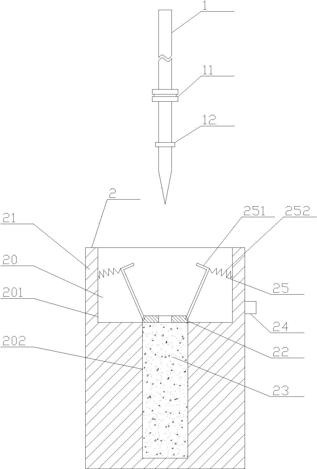
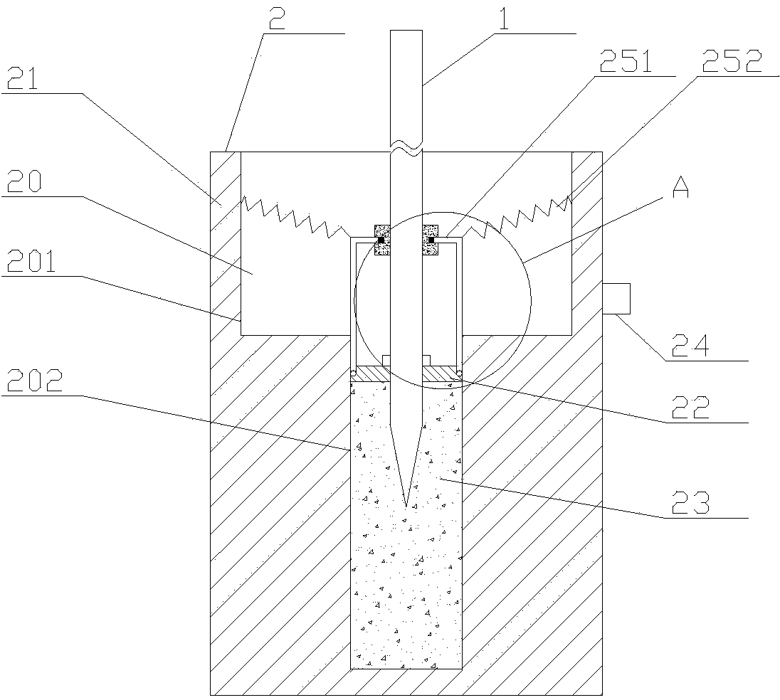
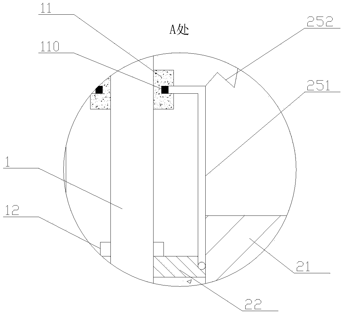
[0036] Embodiment one, such as Figure 1-3 As shown: the trigger assembly 25 includes a trigger lever 251 and a tension spring 252. The trigger lever 251 is in an inverted L shape and is made of conductive material. The trigger lever 251 is connected in series to the power supply Between the indicator light 24 , the trigger lever 1 251 includes a long rod and a short rod connected as one and perpendicular to each other, the bottom end of the long rod is hinged in the accommodation groove 222 of the clamp 22 , The tension spring one 252 is connected between the top end of the long rod and the inner wall of the upper slot 201 . Like this, when clamping plate moves downwards under the drive of grounding pin, a pair of long rods will break away from the pulling force of extension spring one under the effect of the notch of lower groove and turn upwards, thereby drive short rods to move together, and then make a pair of The short rod extends into the contact groove to make contact...

Embodiment 2

[0038] Embodiment two, such as Figure 7-9 As shown: the trigger assembly 25 includes a trigger lever 2 253, a tension spring 2 and a slide bar 255, the upper part of the trigger lever 2 253 is arc-shaped, and the bottom end of the trigger lever 2 253 is hinged on the In the accommodating groove 222, the trigger rod 253 is made of conductive material, the trigger rod 253 is connected in series between the power supply and the indicator light 24, the sliding rod 255 is semicircular, and The two ends of the slide bar 255 in a pair of trigger assemblies 25 are fixedly connected to each other, the slide bar 255 is accommodated on the top of the trigger lever 253, and the extension spring 2 is connected between the trigger lever 2 253 and the trigger lever 253. between the groove bottoms of the upper groove 201. Like this, when clamping plate moves downwards under the drive of ground pin, a pair of trigger lever two will want to upturn under the effect of the notch of lower groove...

Embodiment 3

[0040] Embodiment three, such as Figure 10-12 As shown: the trigger assembly 25 includes a trigger lever three 256 and a trigger lever four 257, the bottom end of the trigger lever three 256 is hinged in the accommodating groove 222 of the clamp 22, and the top end of the trigger lever three 256 is hinged In the middle part of the trigger lever 257, the bottom end of the trigger lever 257 is hinged on the inner wall of the upper groove 201. The trigger lever 257 is made of conductive material and connected in series between the power supply and the indication between lamps 24 . Like this, when clamping plate moves downwards under the drive of grounding pin, a pair of trigger rods 3 will turn up under the effect of the notch of the lower groove, thereby drive trigger rod 4 to turn down, and then make a pair of trigger rods 4 The top end of the pin extends into the contact groove to achieve contact with the contact piece, and finally lights up the indicator light; after the cl...


PUM


Abstract

The invention relates to the field of electric power engineering, and provides a grounding pile which is a temporary grounding device simple in structure, convenient to use, low in operation difficulty and high in reliability. According to the technical scheme, the grounding pile is used for containing a grounding pin, and a contact ring and a limiting ring are sequentially arranged at the lower end of the grounding pin from the top to bottom. The grounding pile comprises a pile body, a clamping plate, a pluggable block, a power supply, an indicator light and a pair of trigger components, wherein the outer edge of the clamping plate is provided with a pair of symmetric containing grooves, the indicator light is detachably connected to the outer wall of the pile body, a contact chip is in contact through the top ends of the trigger components, so that the indicator light is turned on. The grounding pile has the advantages of being convenient to use, low in operation difficulty and high in reliability and accuracy.

Description

technical field [0001] The invention relates to the field of electric power engineering. Background technique [0002] The grounding pile is used as a storage platform for the grounding needle in the power line or equipment when it is idle, and its correct use and management are particularly important. There are clear regulations in the electrical safety work regulations: each grounding pin should be numbered and stored in a fixed location, and the storage location should also be numbered. The number on the grounding needle must be consistent with the number on the storage location; The ground terminal must be connected first and then the conductor segment, and must be in good contact; while the order of removing the ground pin is the opposite. It can be seen that it is very important that the grounding pins are correctly inserted on the grounding stakes or kept in the designated temporary grounding pin storage area. [0003] In the traditional operation method, when the g...

Claims


Application Information

Patent Timeline
IPC IPC(8): B65D85/24
Inventor 张伟
Owner 国网江苏省电力有限公司高邮市供电分公司
Why Eureka
Try Eureka