Two-way hard sealing butterfly valve with movable valve seat

A mobile, hard-sealed technology, applied in the direction of lift valves, valve devices, engine components, etc., can solve problems affecting the long-term normal operation of pipelines, high production costs, and bellows are easily damaged by water immersion, and achieve good hard-sealed effects. Long service life, guarantee the effect of hard sealing effect

Inactive Publication Date: 2014-08-20
ANHUI TONGDU FLOW TECH
View PDF9 Cites 7 Cited by
  • Summary
  • Abstract
  • Description
  • Claims
  • Application Information

AI Technical Summary

Problems solved by technology

[0003] The technical problem to be solved by the present invention is that the existing butterfly valve with movable sealing surface has high production cost and the corrugated pipe is easily damaged by immersion in water, which affects the long-term normal operation of the pipeline. For this purpose, a two-way hard-sealed butterfly valve with movable valve seat is provided.

Method used


Image

  • Two-way hard sealing butterfly valve with movable valve seat
  • Two-way hard sealing butterfly valve with movable valve seat
  • Two-way hard sealing butterfly valve with movable valve seat

Examples


Embodiment Construction

[0018] The present invention will be further described below in conjunction with the accompanying drawings.

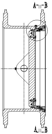
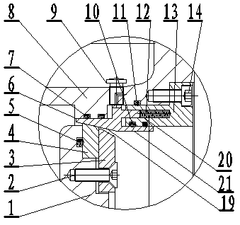
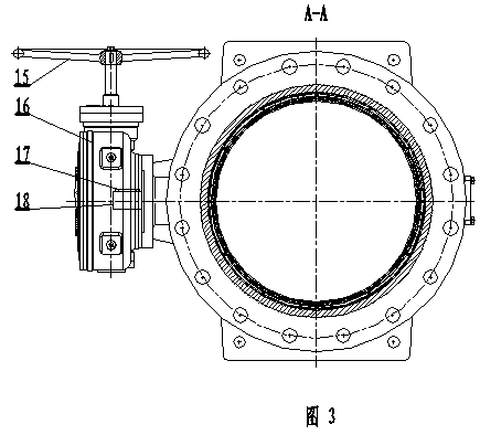
[0019] Such as Figure 1-Figure 6 As shown, the present invention includes a valve body 8, a valve seat 6, a butterfly plate 1, a hand wheel 15, a worm gear box 16, a key 17 and a valve shaft 18, and the butterfly plate 1 is fixedly connected with a pressure plate 3 through a pressure plate screw 2. A butterfly plate sealing ring 4 is provided between the pressure plate 3 and the butterfly plate 1, and a valve seat 6 is provided between the butterfly plate sealing ring 4 and the valve body 8, and the valve seat is divided into a clamping portion 19 extending horizontally and inversely. And the support arm part, the joint between the clamping part 19 and the top of the butterfly plate sealing ring 4 is a slope, the joint between the clamping part 19 and the valve body 8 is a plane, and the support arm part includes first The support arm 20 and the second support arm 21...


PUM


Abstract

The invention discloses a two-way hard sealing butterfly valve with a movable valve seat. The two-way hard sealing butterfly valve comprises a valve body, the valve seat, a butterfly plate, a hand wheel, a worm gear case, a key and a valve shaft. The butterfly plate is fixedly connected with a press plate through a press plate screw. A butterfly plate seal ring is arranged between the press plate and the butterfly plate. The valve seat is arranged between the butterfly plate seal ring and the valve body. The valve seat comprises a horizontally reversely extended clamping part and a support arm part. The matching part between the clamping part and the top of the butterfly plate seal ring is a slope. The support arm part comprises a first support arm and a second support arm, wherein the first support arm and the second support arm are arranged in parallel in a spaced mode. The inner side wall of the valve body is fixedly connected with a pressing sleeve which extends horizontally to the support arm part. The tail end of the pressing sleeve is provided with a groove. A compressed spring set which is arranged horizontally is arranged in the groove. The tail end of the first support arm is arranged in the groove in a matching mode and makes contact with the compressed spring set. The two-way hard sealing butterfly valve has the advantages that the valve seat is horizontally positioned at many positions, and therefore the valve seat will not tilt in the moving process; as a plurality of O-type rings are arranged, the compressed spring set operates in a clean environment, and service life is long; the compressed spring set composed of a plurality of compressed springs is adopted, so that production cost is lowered; an exhaust cap and the movable valve seat allow the operation torque of the butterfly plate to be low.

Description

technical field [0001] The invention relates to a butterfly valve, in particular to a two-way hard-sealed butterfly valve with a movable valve seat. Background technique [0002] At present, butterfly valves are small in size, light in weight, and small in installation size. They are widely used in various pipelines such as water supply and drainage, metallurgy, petroleum, chemical industry, and electric power to regulate or cut off the fluid in the pipeline. Therefore, valve professionals have done more research on butterfly valves. The valve plate and sealing structure of the butterfly valve have always been a subject of research by valve technicians. The existing hard-sealed butterfly valve usually adopts a fixed seal in terms of sealing structure. This fixed sealing structure makes the opening and closing of the butterfly plate generate a lot of friction, increases the torque for opening and closing the valve, and is difficult to process. Large, the butterfly plate and...

Claims


Application Information

Patent Timeline
Patent Type & Authority Applications(China)
IPC IPC(8): F16K1/226F16K1/46F16K1/36
CPCF16K1/2261F16K1/222F16K1/2263F16K1/42
Inventor 汪班本
Owner ANHUI TONGDU FLOW TECH
Why Eureka
Try Eureka