Pressure relief valve

A technology for releasing valve and pressure, applied in the field of pressure release valve, it can solve the problems of inability to spring back and use, spring deformation, spring corrosion, etc., and achieve the effect of facilitating on-site installation and preventing deformation

Active Publication Date: 2014-08-20
JIANGSU HAOCHEN MACHINERY MFG
View PDF6 Cites 2 Cited by
  • Summary
  • Abstract
  • Description
  • Claims
  • Application Information

AI Technical Summary

Problems solved by technology

[0002] At present, the existing pressure release valve has poor rainproof and moisture-proof performance, which leads to spring corrosion. When the ejection pressure is too high, the spring is deformed and cannot be rebounded and used.

Method used


Image

  • Pressure relief valve

Examples


Embodiment Construction

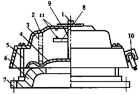
[0013] The present invention will be further described below in conjunction with the accompanying drawings.

[0014] Such as figure 1 As shown, a pressure relief valve includes a valve seat 6, a film disc 4, a spring 3, and also includes a mounting flange 7, a shield 2, and a screw rod 5. The bottom of the valve seat 6 is provided with a mounting flange 7 for use For the convenience of connecting with the oil conservator; the top of the valve seat 6 is provided with a film disc 4, the top of the film disc 4 is connected to one end of the spring 3, and the other end of the spring 3 is connected to the inner wall of the shield 2; the valve seat Mounting holes are provided on both sides of 6, and the shield 2 is set above the valve seat 6 through the mounting holes on the screw rod 5 and the valve seat 6.

[0015] Also includes a sign shaft 1, the bottom end of the sign shaft 1 is connected to the central top of the film disc 4, the other end of the sign shaft 1 passes through t...


PUM


Abstract

The invention discloses a pressure relief valve. The pressure relief valve comprises a valve base, an adhesive film disc, a spring, an installation flange, a protecting cover and screws. The installation flange is arranged at the bottom of the valve base and used for being conveniently connected with an oil conservator. The adhesive film disc is arranged at the top of the valve base, the top of the adhesive film disc is connected with one end of the spring, and the other end of the spring is connected with the inner wall of the protecting cover. The two sides of the valve base are provided with installation holes, and the protecting cover is arranged above the valve base through the screws and the installation holes in the valve base. According to the pressure relief valve, through the design of the installation flange, on-site installation is facilitated; the protecting cover can effectively prevent rain and damp; through the design of a baffle, the risk that the spring deforms due to overlarge ejection pressure can be effectively avoided; an interface for remote monitoring is provided.

Description

technical field [0001] The invention relates to a pressure relief valve, which belongs to the technical field of transformer safety devices. Background technique [0002] At present, due to poor rainproof and moistureproof performance of the existing pressure release valve, the spring is corroded. When the ejection pressure is too high, the spring is deformed and cannot be rebounded and used. Contents of the invention [0003] Purpose: In order to overcome the deficiencies in the prior art, the present invention provides a pressure release valve. [0004] Technical solution: In order to solve the above-mentioned technical problems, the technical solution adopted in the present invention is: [0005] A pressure relief valve, including a valve seat, a film disc, a spring, and also includes a mounting flange, a shield, and a screw rod. The bottom of the valve seat is provided with a mounting flange for easy connection with an oil conservator; the valve There is a film disk ...

Claims


Application Information

Patent Timeline
IPC IPC(8): F16K17/04F16K27/08H01F27/00
CPCF16K17/04F16K27/02F16K27/08F16K37/0025
Inventor 任育文
Owner JIANGSU HAOCHEN MACHINERY MFG
Why Eureka
Try Eureka