
Boom drive device

一种驱动装置、动臂的技术,应用在流体压力致动装置、机器/发动机、流体压力致动系统组件等方向,能够解决变小、难以付与不适感等问题

Inactive Publication Date: 2014-08-20
KYB CORP
View PDF7 Cites 5 Cited by
  • Summary
  • Abstract
  • Description
  • Claims
  • Application Information

AI Technical Summary

Problems solved by technology

Conversely, if the lowering speed of the boom is high, since the return flow discharged from the piston side chamber is originally large, the ratio of the flow rate that changes with the activation of the fluid pressure motor is relatively small, so it is difficult to give discomfort.

Method used


Image

  • Boom drive device
  • Boom drive device
  • Boom drive device

Examples


Embodiment Construction

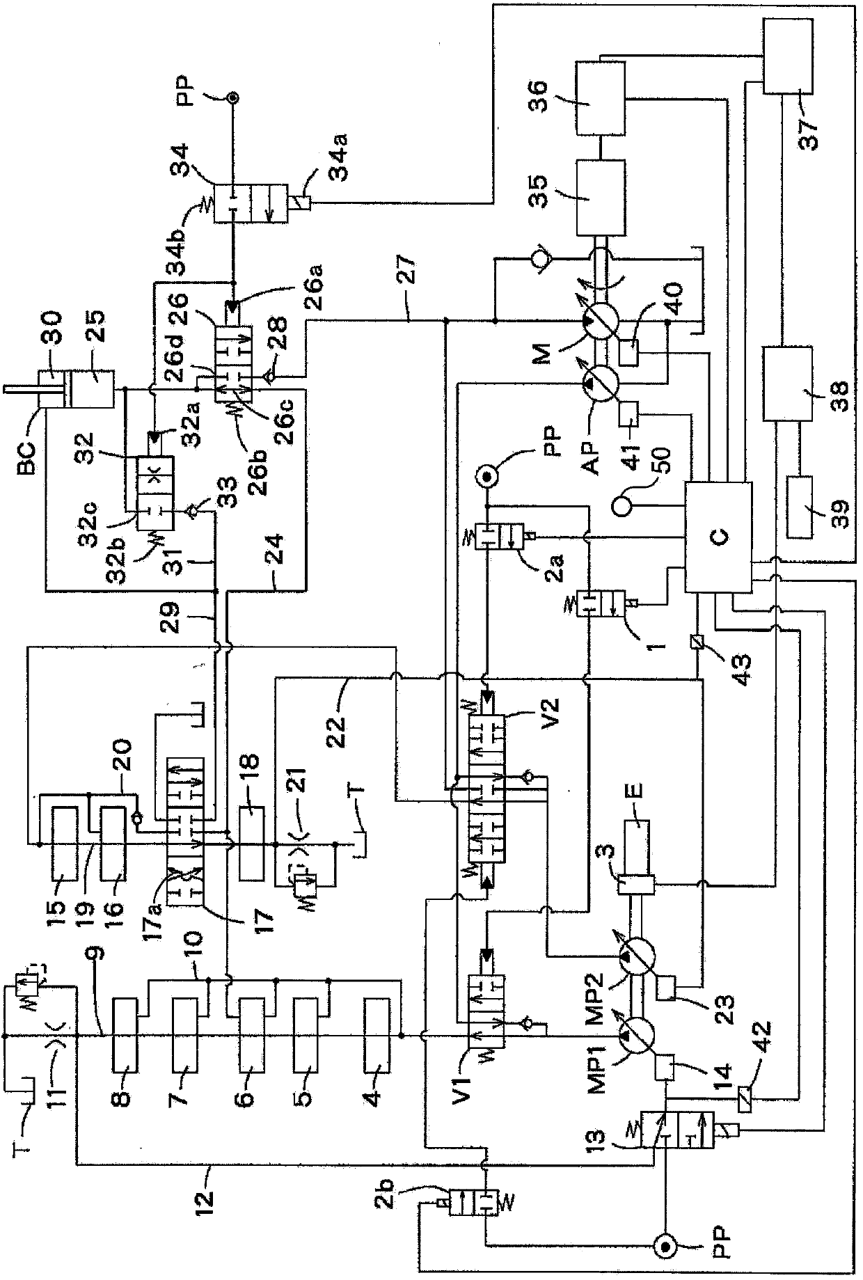
[0024] refer to figure 1 , The boom driving device of the present invention includes a variable displacement first main pump MP1, a variable displacement second main pump MP2, and a variable displacement auxiliary pump AP. The discharge port of the first main pump MP1 is connected to the first circuit system through the first switching valve V1. The discharge port of the second main pump MP2 is connected to the second circuit system through the second switching valve V2. The discharge port of the auxiliary pump AP joins the discharge port of the first main pump MP1 via the first switching valve V1. The first main pump MP1, the second main pump MP2, and the auxiliary pump AP are all constituted by pumps that pressurize and supply working oil.

[0025] In the following description, there will be no external energy supply for valves that operate based on external energy supply, such as solenoid valves operated by solenoid excitation and pilot valves operated by pilot pressure. ...


PUM


Abstract

This boom drive device is provided with a boom switching valve for extending and retracting a boom hydraulic cylinder. When the boom switching valve is in a lowering position in which lowering operations are performed, work fluid discharged from the working chamber of the boom hydraulic cylinder is recirculated to a tank. A portion of the discharged work fluid is separated upstream of the boom switching valve, supplied through a regenerative passage to a generator, and used in power generation in the generator. A regeneration control spool valve is provided in the regenerative passage. When the boom switching valve is switched to the lowering position, after the flow cross-sectional area of the work fluid flowing from the work chamber to the tank has reached a prescribed level, the shock accompanying power generation start in the generator is lessened by opening the regeneration control spool valve.

Description

technical field [0001] The present invention relates to control of a boom drive device that performs regenerative power generation using return fluid from a boom cylinder that raises or lowers a boom. Background technique [0002] Construction equipment with a boom typically includes a boom cylinder that turns the boom up and down. JP2011-179541A issued by the Japanese Patent Office proposes a recovery power generation device, which uses the return fluid from the boom cylinder when the boom is turned downward to rotate the fluid pressure motor, and utilizes the rotational torque of the fluid pressure motor Drive the generator. [0003] The boom cylinder has a rod-side chamber formed by a piston and a piston-side chamber on the opposite side. The working oil is selectively supplied to one of the rod side chamber and the piston side chamber via a switching valve that switches according to the operating direction of the boom cylinder. In addition, the switching valve also co...

Claims


Application Information

Patent Timeline
Patent Type & Authority Applications(China)
IPC IPC(8): F15B21/14E02F9/22
CPCF15B2211/88E02F9/2217E02F9/2292F04B7/02F15B2211/31558E02F9/2207F15B2211/634F15B15/20E02F9/2296F15B2211/7058E02F9/2282F15B21/14F15B2211/30565E02F9/2075F15B2211/7053F15B2211/665F15B2211/8606F15B2211/3058F15B2013/0409E02F9/22
Inventor 江川祐弘川崎治彦米原康裕
Owner KYB CORP
Features
  • Generate Ideas
  • Intellectual Property
  • Life Sciences
  • Materials
  • Tech Scout
  • Unparalleled Data Quality
  • Higher Quality Content
  • 60% Fewer Hallucinations
Learn More