Fixed positioning device for rear parts of aircraft products

A positioning device, fixed technology, applied in the direction of positioning device, workpiece clamping device, aircraft assembly, etc., can solve the problems of large deformation, out-of-tolerance of the unevenness of the connector head, and delamination of composite materials, etc. The effect of small area, large working space and convenient combination

Active Publication Date: 2016-08-17
TSINGHUA UNIV +1
View PDF6 Cites 0 Cited by
  • Summary
  • Abstract
  • Description
  • Claims
  • Application Information

AI Technical Summary

Problems solved by technology

[0002] At present, the assembly of aircraft mainly relies on traditional manual assembly methods, combined with some targeted control measures, which can improve the quality of aircraft assembly to a certain extent, but there is still a considerable gap from the demanding assembly quality technical indicators of advanced aircraft, mainly reflected in: large size It is not easy to guarantee the assembly accuracy of the frame beam frame
Since the maximum size of the frame parts is more than 4 meters, the deformation of the parts during the manufacturing and assembly process is relatively large, and the assembly process lacks effective detection and control measures, which cannot meet the technical requirements of the design; composite material / titanium alloy, composite material / aluminum alloy It is very difficult to make holes in the laminated structure. Manual hole making requires extremely high operating skills of workers, and the hole making efficiency is low. It is prone to layering of composite materials, elliptical diameters, and connector heads caused by inclined hole positions and inaccurate nesting depths. The unevenness of the surface is out of tolerance, seriously affecting the performance of the aircraft
[0003] The current situation of aircraft assembly shows that traditional manual assembly technology can no longer meet the assembly quality requirements of advanced aircraft, and it is necessary to fundamentally change the assembly technology, and digital assembly has become an inevitable choice
The key part of automatic hole-making digital assembly, the assembly of the rear parts of the existing aircraft products adopts closed tooling, but due to the problem of space interference, the automatic hole-making with CNC machine tools cannot be realized. Therefore, the layout of the existing closed tooling must be modified , to meet the operating space required for automatic hole making

Method used


Image

  • Fixed positioning device for rear parts of aircraft products
  • Fixed positioning device for rear parts of aircraft products
  • Fixed positioning device for rear parts of aircraft products

Examples


Embodiment Construction

[0016] The open assembly and positioning system for the rear part of aircraft products provided by the present invention will be further described in detail below in conjunction with the accompanying drawings and specific embodiments.

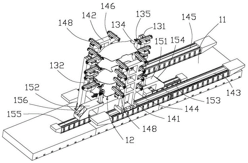
[0017] see figure 1 , the first embodiment of the present invention provides an open assembly and positioning system for the rear part of the aircraft product, which has the functions of assembling, positioning and fixing the frame of the rear part of the aircraft product, so that each part of the aircraft product frame maintains an accurate relative position, and provides The strength, rigidity and spatial position required for subsequent operations on the rear parts of aircraft products, for example, to provide the operation space required for the automatic hole making of subsequent CNC machine tools.

[0018] The open assembly and positioning system for rear parts of aircraft products includes a central workbench 11, a bottom support positio...


PUM


Abstract

The invention relates to a fixed positioning device of a rear section part of an aircraft product. The fixed positioning device comprises a first fixed positioning device and a second fixed positioning device; the first fixed positioning device comprises a comb-shaped positioning support and a plurality of positioners, wherein the plurality of positioners are arranged on the comb-shaped positioning support; the second fixed positioning device comprises a comb-shaped positioning support and a plurality of positioners, wherein the plurality of positioners are arranged on the comb-shaped positioning support; the first fixed positioning device and the second fixed positioning device are arranged oppositely and accordingly the rear section part of the aircraft product and to be positioned can be positioned.

Description

technical field [0001] The invention relates to an automatic manufacturing equipment, in particular to a fixed positioning device for the rear part of an aircraft product. Background technique [0002] At present, the assembly of aircraft mainly relies on traditional manual assembly methods, combined with some targeted control measures, which can improve the quality of aircraft assembly to a certain extent, but there is still a considerable gap from the demanding assembly quality technical indicators of advanced aircraft, mainly reflected in: large size The assembly accuracy of the frame-beam frame is not easy to guarantee. Since the maximum size of the frame parts is more than 4 meters, the deformation of the parts during the manufacturing and assembly process is relatively large, and the assembly process lacks effective detection and control measures, which cannot meet the technical requirements of the design; composite material / titanium alloy, composite material / aluminum ...

Claims


Application Information

Patent Timeline
Patent Type & Authority Patents(China)
IPC IPC(8): B25B11/02B23Q3/06
CPCB23Q3/06B25B11/02B64F5/10
Inventor 陈恳帅朝林陈雪梅吴丹詹有河熊钦林曾秀玉王国磊徐静杨向东宋立滨周凯付成龙刘莉
Owner TSINGHUA UNIV
Why Eureka
Try Eureka