Mechanism for opening mold step by step through sliding block locked by fixed mold positioning pin
A technology of positioning nails and sliders, which is applied in the field of plastic product manufacturing molds, can solve the problems of broken features, small area, and unsmooth forming of products, and achieve the effect of preventing damage and improving molding quality
- Summary
- Abstract
- Description
- Claims
- Application Information
AI Technical Summary
Problems solved by technology
Method used
Image

Examples
Embodiment Construction
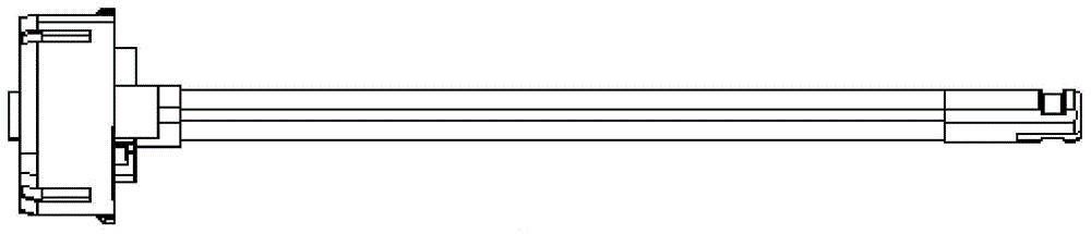
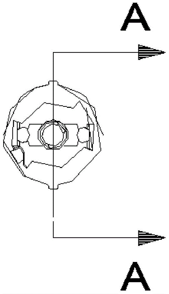
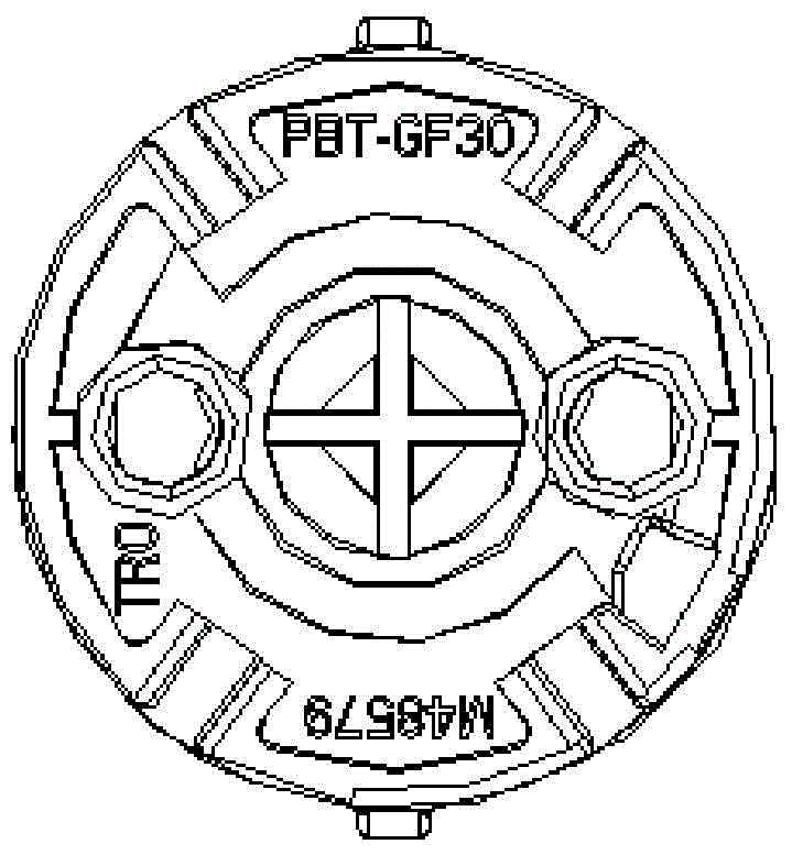
[0054] Refer to attached Figure 5a — attached Figure 13 , the part numbers in each figure are as follows:
[0055] 1. Moving template 2, inclined guide column 3, fixed template 4, locking block 5, movable mold core 6, fixed mold core 7, plastic product 8, slider block 9, slider core 10, slider Seat 11, slider platen 12 locating nail fixing screw 13 locating nail 14 spring 15 first screw 16 spring 17 first screw 18 slider core fixing block 19 second screw
[0056] The sliding block step-by-step mold opening mechanism locked by the fixed mold positioning nails according to the present invention comprises a matched movable template 1 and a fixed template 3, the movable template 1 is provided with a movable mold core 5, and the fixed template 3 is provided with a fixed template. The mold core 6, the parting surface between the movable mold core 5 and the fixed mold core 6 is provided with a molding cavity for plastic products, the molding cavity is connected to the pouring mec...
PUM
 Abstract
Description
Claims
Application Information
 - R&D
- Intellectual Property
- Life Sciences
- Materials
- Tech Scout
- Unparalleled Data Quality
- Higher Quality Content
- 60% Fewer Hallucinations
Browse by: Latest US Patents, China's latest patents, Technical Efficacy Thesaurus, Application Domain, Technology Topic, Popular Technical Reports.
© 2025 PatSnap. All rights reserved.Legal|Privacy policy|Modern Slavery Act Transparency Statement|Sitemap|About US| Contact US: help@patsnap.com