Connection structure of escalator truss
A technology for escalators and trusses, applied in escalators, transportation and packaging, etc., which can solve problems such as installation difficulties, space waste, and cost increases, and achieve the effects of easy connection installation, reduced costs, and reduced deformation
- Summary
- Abstract
- Description
- Claims
- Application Information
AI Technical Summary
Problems solved by technology
Method used
Image

Examples
Embodiment 1
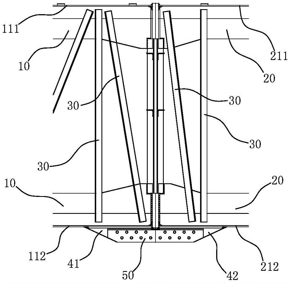
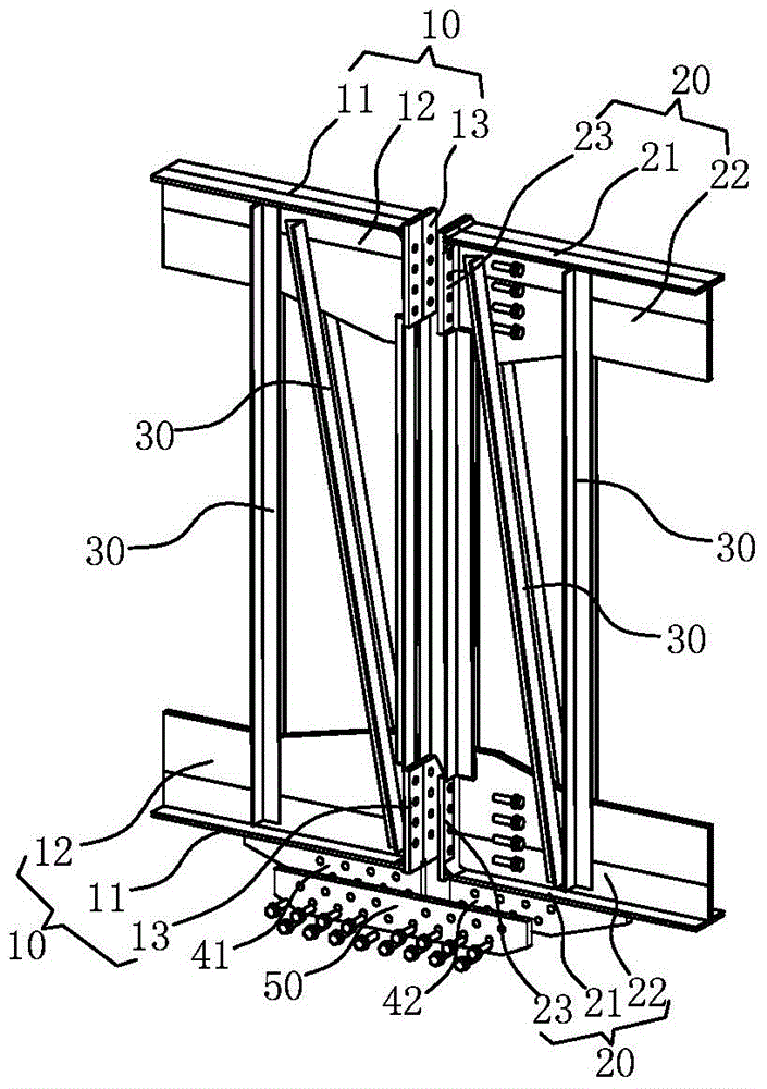
[0026] like Figure 1 to Figure 2 As shown, a docking structure of an escalator truss includes a first split truss and a second split truss, the first split truss includes two first main chords 10, and the two first main chords 10 are parallel to each other or substantially parallel, and the two first main chords 10 are connected by connecting beams 30, the second split truss includes two second main chords 20, the two second main chords 20 are parallel or substantially parallel to each other, And the two second main chords 20 are also connected by connecting beams 30 . The first main string 10 includes a first main body part 12, a first connecting end plate 13 and a first side edge 11. The first connecting end plate 13 and the first side edge 11 are fixedly arranged on the first main body part 12. The second main string 20 includes a second main body portion 22 , a second connecting end plate 23 and a second side edge 21 . A connecting end plate 13 and the corresponding sec...
Embodiment 2
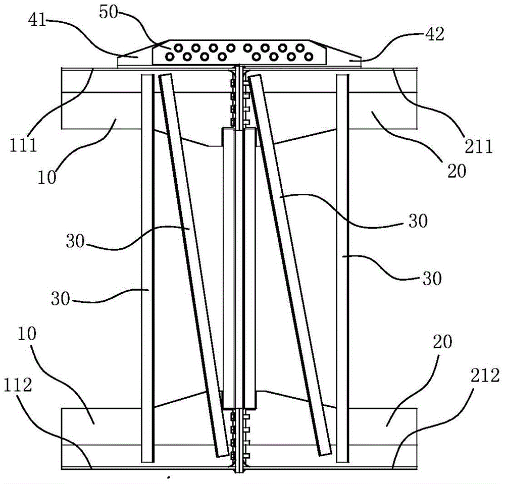
[0029] like image 3 As shown, the difference between this embodiment and the first embodiment is that the first fixed reinforcing plate 41 is only fixedly connected to the first upper side, and the first fixed reinforcing plate 41 is located on the outer side of the first upper side, which is image 3 The upper side of the first upper side edge, and the second fixed reinforcing plate 42 is only fixedly connected to the outer side of the second upper side edge, namely image 3 The upper side of the middle second upper side. Other structures in this embodiment are the same as those in Embodiment 1, and are not repeated here.
Embodiment 3
[0031] like Figure 4 As shown in the figure, the difference between this embodiment and the first embodiment is that the first fixed reinforcing plate 41 is fixedly connected on the first upper side and the first lower side, and the second upper side and the second The second fixed reinforcing plate 42 is fixedly connected to the lower side, and the first fixed reinforcing plate 41 on the first upper side is located on the outer side of the first upper side, namely Figure 4 On the upper side of the first upper side edge, the first fixed reinforcing plate 41 on the first lower side edge is located on the outer side of the first lower side edge, namely Figure 4 The lower side of the first lower side edge, and the second fixed reinforcing plate 42 on the second upper side edge is located on the outer side of the second upper side edge, namely Figure 4 The upper side of the middle second upper side edge, the second fixed reinforcing plate 42 on the second lower side edge is l...
PUM
 Abstract
Description
Claims
Application Information
 - R&D
- Intellectual Property
- Life Sciences
- Materials
- Tech Scout
- Unparalleled Data Quality
- Higher Quality Content
- 60% Fewer Hallucinations
Browse by: Latest US Patents, China's latest patents, Technical Efficacy Thesaurus, Application Domain, Technology Topic, Popular Technical Reports.
© 2025 PatSnap. All rights reserved.Legal|Privacy policy|Modern Slavery Act Transparency Statement|Sitemap|About US| Contact US: help@patsnap.com