Supercharge Your Innovation With Domain-Expert AI Agents!

A design method of multi-vane non-clogging pump impeller

A technology of non-clogging pumps and design methods, which is applied in the direction of non-variable pumps, pumps, pump components, etc., can solve the problems of reduced passing area, increased cost, and burned motors, and achieves increased effective working area, high efficiency and The effect of improving head and prolonging service life

Active Publication Date: 2016-09-14
JIANGSU UNIV
View PDF7 Cites 0 Cited by
  • Summary
  • Abstract
  • Description
  • Claims
  • Application Information

AI Technical Summary

Problems solved by technology

This type of pump has circulating flow and through flow in the pump cavity at the same time, the hydraulic loss is large, and the efficiency is often low. When this type of pump is running, the power is easily overloaded in the large flow area and the motor will be burned.
[0004] After retrieval, the published patent "Impeller for non-clogging swirl pump and non-clogging swirl pump" (Application No.: 201220259153.4) has a straight blade shape, and the impeller retracts into the rear pump chamber, so the efficiency is relatively high. Low, and the high-efficiency zone is easy to overload, the pump inlet diameter is small, when conveying the medium containing long fibers, it will cause a certain degree of blockage; the published patent "a semi-open impeller non-blocking cutting pump" (application number: 201120437806.9), which installs a cutter disc for cutting impurities such as large particles and long fibers at the pump inlet, but the structure of the pump becomes complicated and the cost increases when the cutter disc device is installed, and the cutter disc consumes part of the pump when it is running. The efficiency, head and flow rate of the pump are reduced, and the installation of the cutter disc at the pump inlet itself reduces the effective passage area of ​​the pump, reduces the passage capacity of the pump, and causes a certain degree of blockage

Method used


Image

  • A design method of multi-vane non-clogging pump impeller
  • A design method of multi-vane non-clogging pump impeller
  • A design method of multi-vane non-clogging pump impeller

Examples


Embodiment Construction

[0030] The present invention will be further described in detail below in conjunction with the accompanying drawings and specific embodiments: These accompanying drawings are all simplified schematic diagrams, and only illustrate the basic structure of the present invention in a schematic manner.

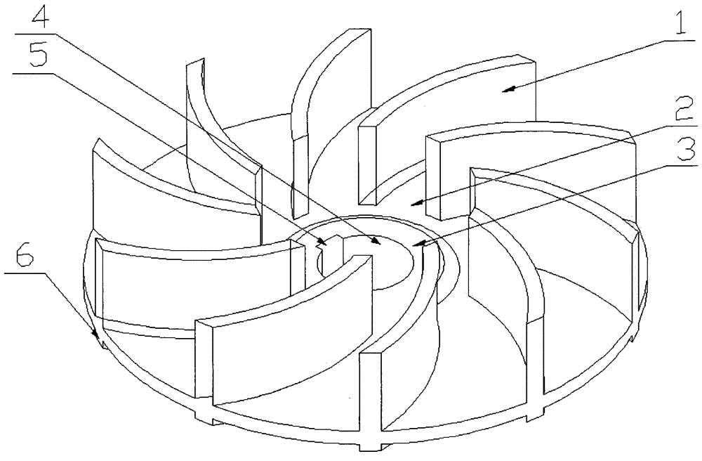
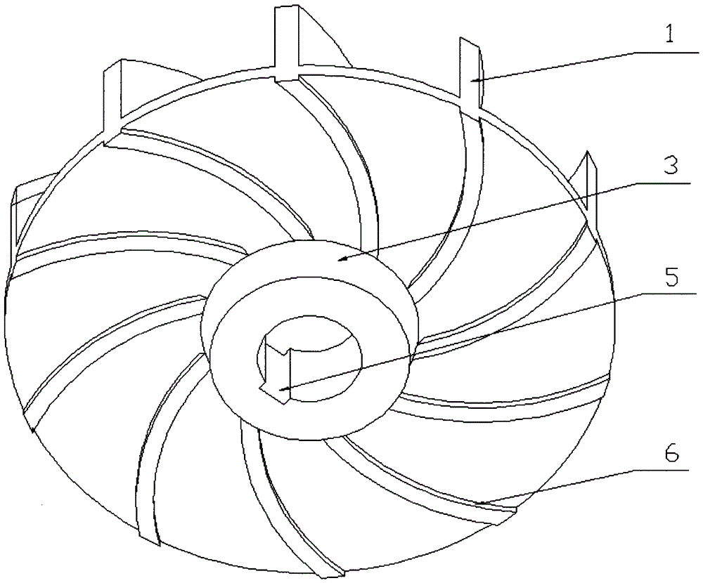
[0031] figure 1 , figure 2 It is a semi-open multi-blade non-clogging impeller, which mainly includes a blade (1), a rear cover plate (2), a wheel body (3), a shaft hole (4), a keyway (5), and auxiliary blades (6). The pump is connected with the drive motor shaft and installed in the volute. When the motor rotates, the warp shaft drives the impeller to rotate, which can realize the transportation of slurry and sewage medium.

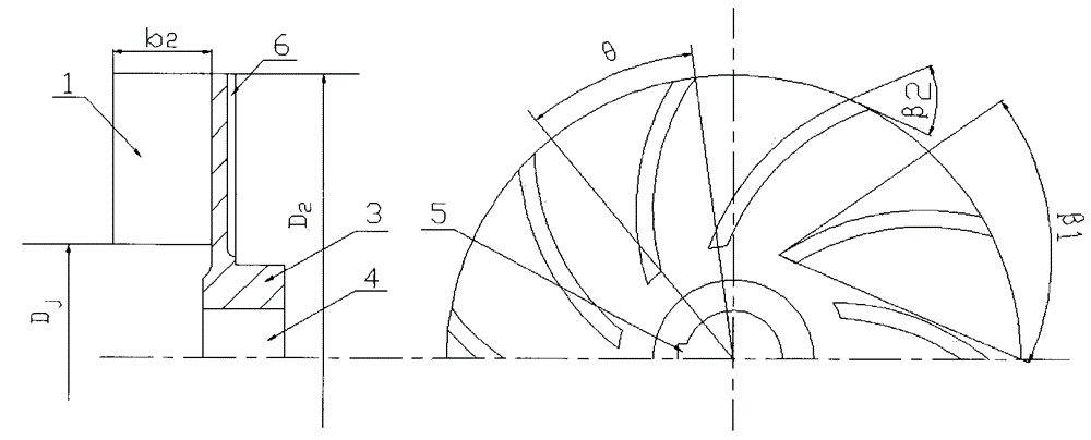
[0032] The impeller outlet diameter D of the present invention 2 Satisfy the following relationship with the design point head H and impeller speed n:

[0033] D 2 = 60 π ...


PUM


Abstract

The invention relates to a method for designing the impeller of a multi-vane non-clogging pump. The invention provides a method for designing a multi-vane non-clogging pump impeller. The non-clogging pump impeller is characterized in that: the impeller is designed as a half-open multi-blade type with only a rear cover (2) and no front cover. The blade (1) is cylindrical in shape, the blade inlet and outlet angles are less than 90°, and the blade inlet diameter is D j Smaller, can effectively reduce the vortex loss in the impeller inlet area, and the impeller is installed in the pump chamber (without retracting to the rear pump chamber), when solid impurities such as long fibers and large particles flow in from the pump inlet, they will be driven by the rotation of the impeller , part of it enters the vaneless chamber, and part of it enters the impeller, and most of the solids entering the impeller are directly sent into the volute under the action of the impeller, thereby reducing the multiple cycles of fibrous particles in the pump chamber, reducing the congestion of the flow channel, and improving The ability to pass through entanglements. The invention has the advantages of simple structure, stable operation, high efficiency and remarkable energy-saving effect.

Description

technical field [0001] The invention relates to a design method of a multi-blade non-clogging pump impeller, in particular to a non-clogging pump impeller mainly suitable for transporting solids with entangled long fibers and large particles, or transporting fluid medium containing part of gas. The utility model belongs to the technical field of slurry and sewage conveying equipment. Background technique [0002] At present, when conveying pulp, sewage and sewage media, the pump is often blocked due to the inclusion of various large particles and long fibers such as long plastic fibers, hemp fibers, pulp fibers and other impurities in the medium, thus affecting the pump's passing performance. and operating efficiency, reducing the reliability and service life of the pump; the fibers wrapped around the impeller not only reduce the effective flow area of ​​the pump and cause blockage, but also require frequent shutdowns for processing and frequent maintenance, which affects wo...

Claims


Application Information

Patent Timeline
Patent Type & Authority Patents(China)
IPC IPC(8): F04D29/22F04D29/24
Inventor 高雄发施卫东张德胜张启华程成
Owner JIANGSU UNIV
Features
  • R&D
  • Intellectual Property
  • Life Sciences
  • Materials
  • Tech Scout
  • Unparalleled Data Quality
  • Higher Quality Content
  • 60% Fewer Hallucinations
Learn More