
Camera adjustment platform for automatic motormeter vision detection device

A technology of automatic detection device and automobile instrument, which is applied in the direction of measuring device, instrument, measuring instrument components, etc., can solve the problem that the camera cannot move three-dimensionally, and achieve the effect of clear image

Active Publication Date: 2014-08-27
HARBIN INST OF TECH
View PDF6 Cites 8 Cited by
  • Summary
  • Abstract
  • Description
  • Claims
  • Application Information

AI Technical Summary

Problems solved by technology

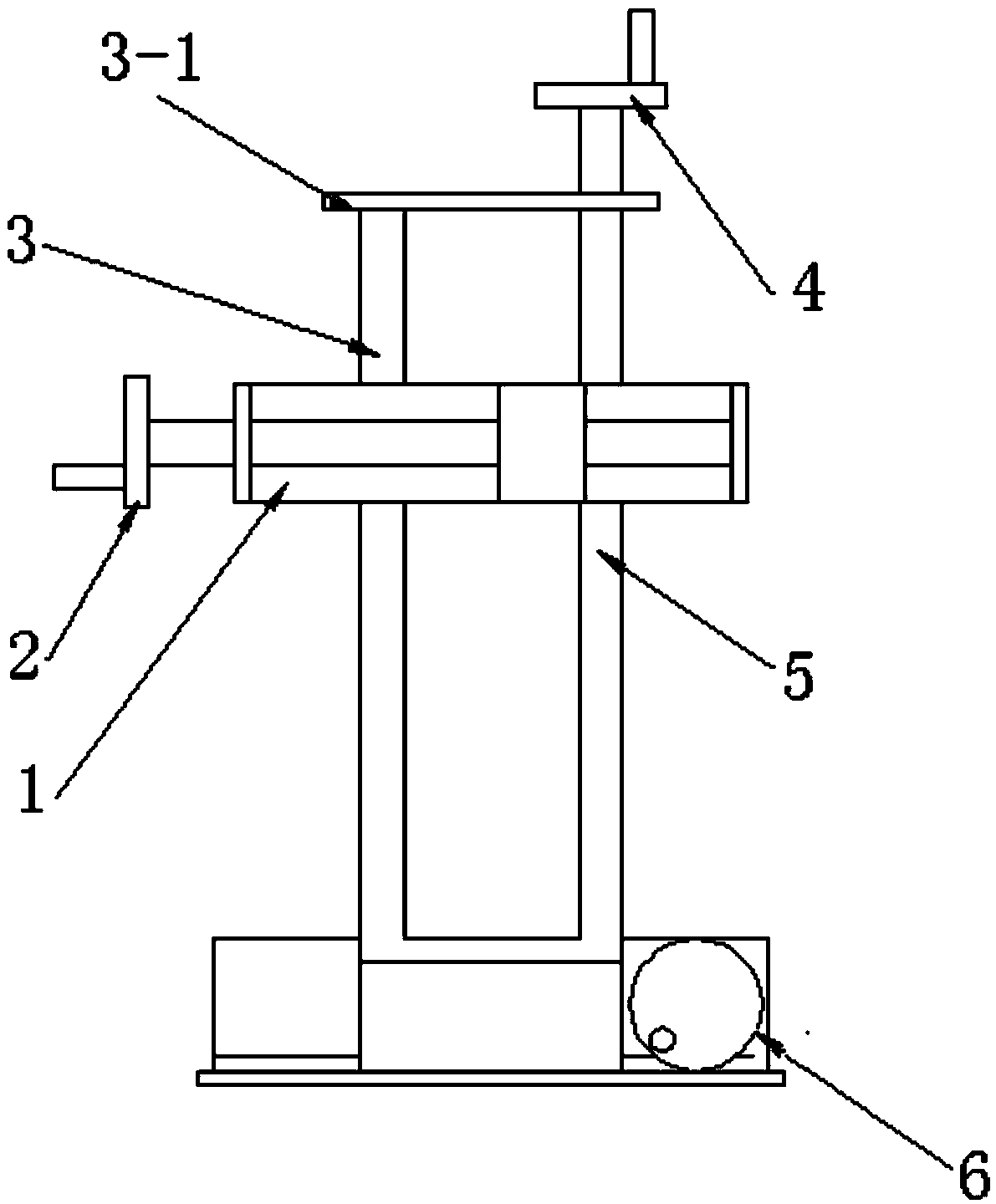
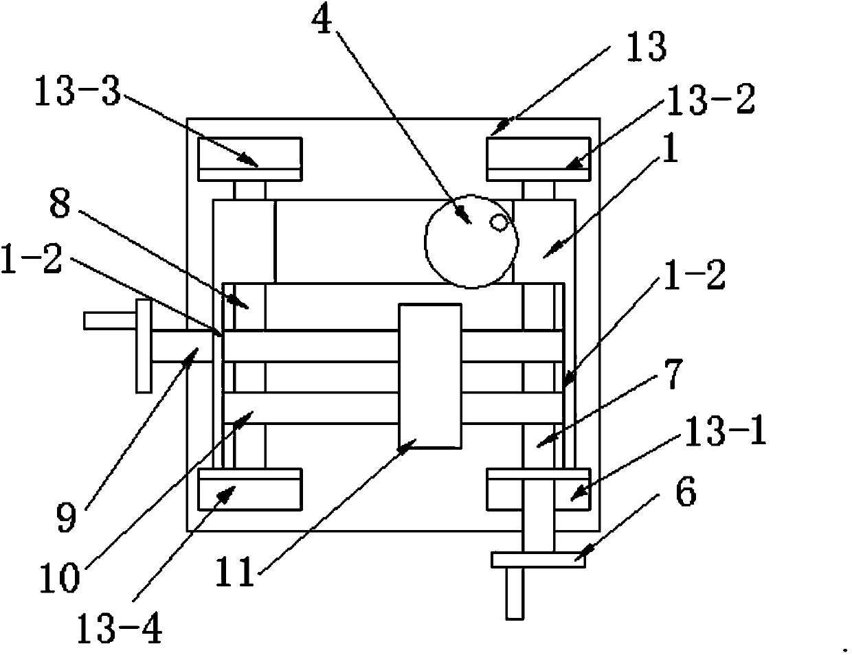
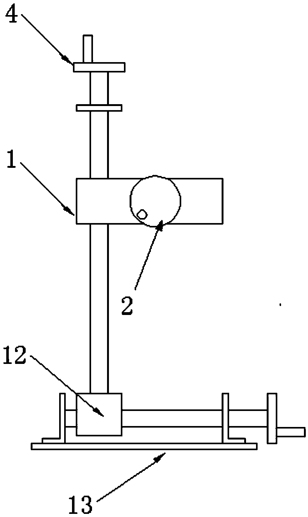
[0004] The invention is considered to solve the problem that the camera in the automatic visual detection device of the automobile instrument cannot move three-dimensionally, and proposes a camera adjustment platform in the automatic visual detection device of the automobile instrument

Method used


Image

  • Camera adjustment platform for automatic motormeter vision detection device
  • Camera adjustment platform for automatic motormeter vision detection device
  • Camera adjustment platform for automatic motormeter vision detection device

Examples


specific Embodiment approach 1

[0014] Specific implementation mode 1. Combination figure 1 , figure 2 and image 3 Describe this embodiment, the camera adjustment platform in the automobile instrument visual automatic detection device described in this embodiment, this platform includes Z-axis slider 1, X-axis handwheel 2, Z-axis guide rod 3, Z-axis handwheel 4, Z-axis Axis screw 5, Y-axis handwheel 6, Y-axis screw 7, Y-axis guide rod 8, X-axis screw 9, X-axis guide rod 10, X-axis slider 11, Y-axis slider 12 and base 13;

[0015] One side of No. 1 angle iron 13-1, No. 2 angle iron 13-2, No. 3 angle iron 13-3 and No. 4 angle iron 13-4 are respectively fixed at the four corners of the upper surface of the base 13, and the Y-axis hand wheel 6 is fixed At one end of the Y-axis lead screw 7, the other end of the Y-axis lead screw 7 passes through the through hole opened on the facade of the first angle iron 13-1, and then is connected with the bearing embedded on the facade of the second angle iron, and the Y...

specific Embodiment approach 2

[0020] Specific embodiment two, this embodiment is a further description of the camera adjustment platform in the automotive instrument vision automatic detection device described in specific embodiment one, the Z-axis guide rod 3 is parallel to the Z-axis lead screw 5, and the Y-axis lead screw 7 is parallel to the Z-axis lead screw 5. The Y-axis guide rod 8 is parallel, and the X-axis lead screw 9 is parallel to the X-axis guide rod 10 .


PUM


Abstract

The invention provides a camera adjustment platform for an automatic motormeter vision detection device, and belongs to the technical field of motormeter detection devices. The camera adjustment platform for the automatic motormeter vision detection device solves the problem that a camera in the automatic motormeter vision detection device cannot be moved in a three dimensional mode. According to the camera adjustment platform, three screw rods are controlled through three sliding wheels, the screw rods rotate and drive sliding blocks to move, the movement direction of the sliding blocks is controlled through a guide rod, the camera is arranged on the X-axis sliding block, and movement of the camera is achieved by rotating the three screw rods. The camera adjustment platform is suitable for the automatic motormeter vision detection device.

Description

technical field [0001] The invention belongs to the technical field of automobile instrument detection equipment. Background technique [0002] With the rapid development of my country's automobile industry, the demand for automobiles has increased year by year, which has brought new opportunities and challenges to the automotive instrumentation industry. Therefore, the automotive instrument industry is constantly pursuing modernization and intelligence in the field, striving to reduce the dependence on workers in the instrument production process, and strive to achieve unmanned. Since the automotive instrument is one of the many components in the design industry of the entire automobile, its detection involves many steps, including the detection of the speed, position, and accuracy of the gauge needle; the brightness and color of various indicator lights detection; and detection of beeps. However, manual detection is not only inefficient, but also increases the probabilit...

Claims


Application Information

Patent Timeline
Patent Type & Authority Applications(China)
IPC IPC(8): G01D11/00
Inventor 高会军于金泳杨承铭由嘉尹珅
Owner HARBIN INST OF TECH
Learn More