
Engine power output rotary shaft torque signal matching box resistance detection circuit

A technology for engine power and resistance detection, applied in the direction of measuring resistance/reactance/impedance, measuring devices, measuring electrical variables, etc., can solve problems such as excessive working current, high temperature, short-circuit damage of external matching box deviation resistance, etc., to achieve Improved efficiency and accurate output voltage

Active Publication Date: 2014-08-27
SICHUAN YAMEI POWER TECH
View PDF5 Cites 2 Cited by
  • Summary
  • Abstract
  • Description
  • Claims
  • Application Information

AI Technical Summary

Problems solved by technology

[0004] The purpose of the present invention is to address the deficiencies in the prior art, to provide an engine power output shaft torque signal matching box that can ensure the output voltage of the shaft torque signal matching box is accurate, and provide convenience for the design and maintenance of the engine and its electronic controller Resistance detection circuit to solve the problem of high temperature caused by excessive working current of the torque signal matching box of the rotating shaft, and short-circuit damage of the deviation resistance of the external matching box

Method used


Image

  • Engine power output rotary shaft torque signal matching box resistance detection circuit
  • Engine power output rotary shaft torque signal matching box resistance detection circuit
  • Engine power output rotary shaft torque signal matching box resistance detection circuit

Examples


Embodiment Construction

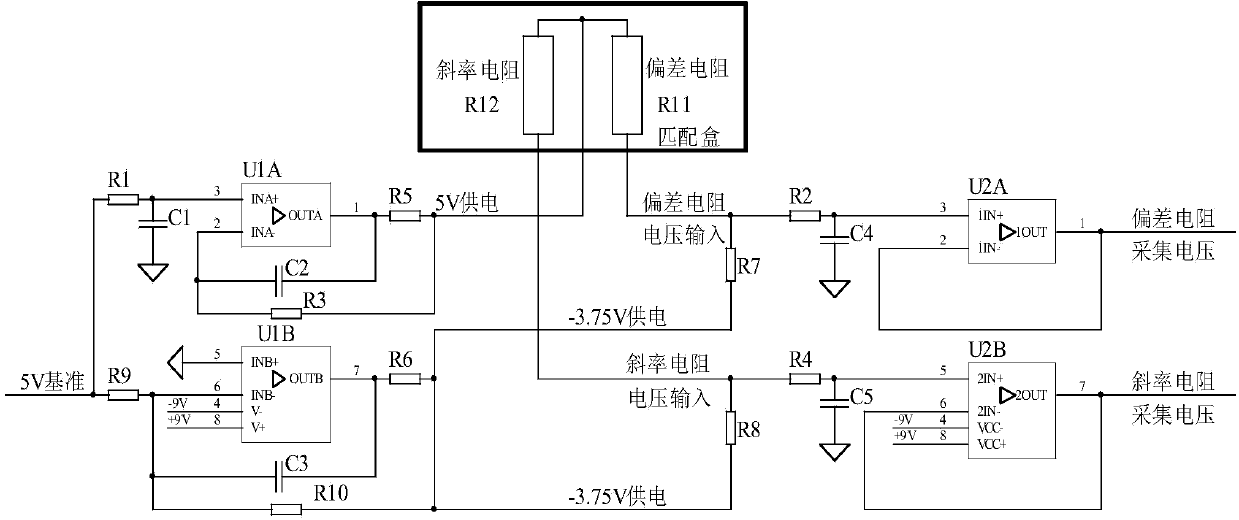
[0013] refer to figure 1 . Engine power output shaft torque signal matching box resistance detection circuit is mainly composed of 5V power supply unit, -3.75V power supply unit, slope resistance detection unit, deviation resistance detection unit and AD conversion unit. The 5V power supply unit sends the 5V reference voltage to the AD conversion unit for digital-to-analog conversion through the slope resistance and the deviation resistance detection unit. The -3.75V power supply unit forms a closed loop through parallel connection of the deviation resistance and the slope resistance. On the contact between the slope resistors, the 5V reference voltage is sent to the AD conversion unit through the slope resistance detection unit for digital-to-analog conversion. The engine electronic controller calculates the deviation resistance and slope according to the voltage converted by the AD conversion unit and the resistance series formula. The resistance value of the resistor.

[...


PUM


Abstract

The invention provides an engine power output rotary shaft torque signal matching box resistance detection circuit. The engine power output rotary shaft torque signal matching box resistance detection circuit comprises a 5 V power supply unit, a -3.75 V power supply unit, a shaft torque signal matching box deviation resistor, a shaft torque signal matching box slope resistor, a slope resistor detection unit, a deviation resistor detection unit and an AD conversion unit. The 5 V power supply unit feeds a 5 V reference voltage to the AD conversion unit through the deviation resistor detection unit and the slope resistor detection unit for digital-to-analog conversion, the -3.75 V power supply unit is connected with the deviation resistor and the slope resistor in parallel to form a closed loop, the deviation resistor is in parallel connection with a connecting point between the 5 V power supply unit and the slope resistor, the 5 V reference voltage is fed to the AD conversion unit through the slope resistor to be processed through digital-to-analog conversion, and an engine electronic controller calculates the resistance value of the deviation resistor and the resistance value of the slope resistor according to the voltage obtained after conversion of the AD conversion unit and a resistor series connection formula. According to the engine power output rotary shaft torque signal matching box resistance detection circuit, the problems that working current of a rotary shaft torque signal matching box is overlarge, high temperature is generated, and an external matching box deviation resistor is damaged due to a short circuit are solved.

Description

technical field [0001] The invention relates to a detection circuit of a thermocouple matching box for monitoring the temperature T45 between an aeroengine gas turbine and a free turbine, and a detection circuit of an aeroengine power output shaft torque signal matching box. Background technique [0002] Torque sensors are also called torque sensors, torque sensors, torque sensors, and torque meters are divided into two categories: dynamic and static. Among them, dynamic torque sensors can also be called torque sensors, torque speed sensors, non-contact torque sensors, rotational torque sensors, etc. . Torque sensors are the detection of torsional torque on various rotating or non-rotating mechanical parts. Torque sensors convert physical changes in torque into precise electrical signals. Torque sensors can be used in the manufacture of viscometers and electric (pneumatic, hydraulic) torque wrenches, which have the advantages of high precision, fast frequency response, goo...

Claims


Application Information

Patent Timeline
Patent Type & Authority Applications(China)
IPC IPC(8): G01R27/14
Inventor 许会元杨志华杨东
Owner SICHUAN YAMEI POWER TECH
Learn More