Method of Generating Parameterized Units

a technology of integrated circuit units and parameterized units, applied in the direction of instruments, computing, electric digital data processing, etc., can solve the problems of difficult script transplantation between different software platforms, inefficient and inadequate, readability and maintainability

Inactive Publication Date: 2014-04-24
SEMITRONIX
View PDF2 Cites 0 Cited by
  • Summary
  • Abstract
  • Description
  • Claims
  • Application Information

AI Technical Summary

Problems solved by technology

Although this method has been commonly practiced in the semiconductor industry, it is in many cases inefficient and inadequate.
The inadequacies of this process include that: (1) For the engineer, designing parameterized unit scripts is very complex, debugging them is difficult, cycle time of the design is long because designing and debugging a parameterized unit requires a lot of time; furthermore, this method requires the engineers to have significant programming skills; (2) for the user of the parameterized units, the scripts represent relatively poor readability and maintainability; (3) different software platform for designing parameterized units has different script syntax and thus parameterized units are dependent on the software platform, therefore it is difficult to realize script transplantation between different software platforms.

Method used


Image

  • Method of Generating Parameterized Units
  • Method of Generating Parameterized Units
  • Method of Generating Parameterized Units

Examples


example 1

The Constraint Relations are Distance Constraint Relations

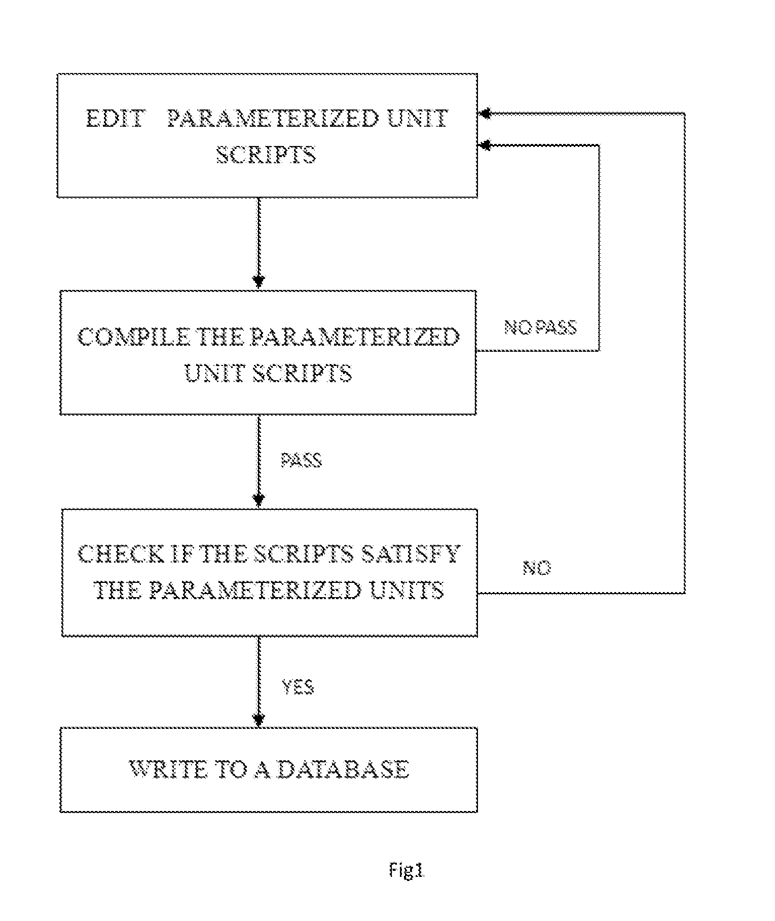
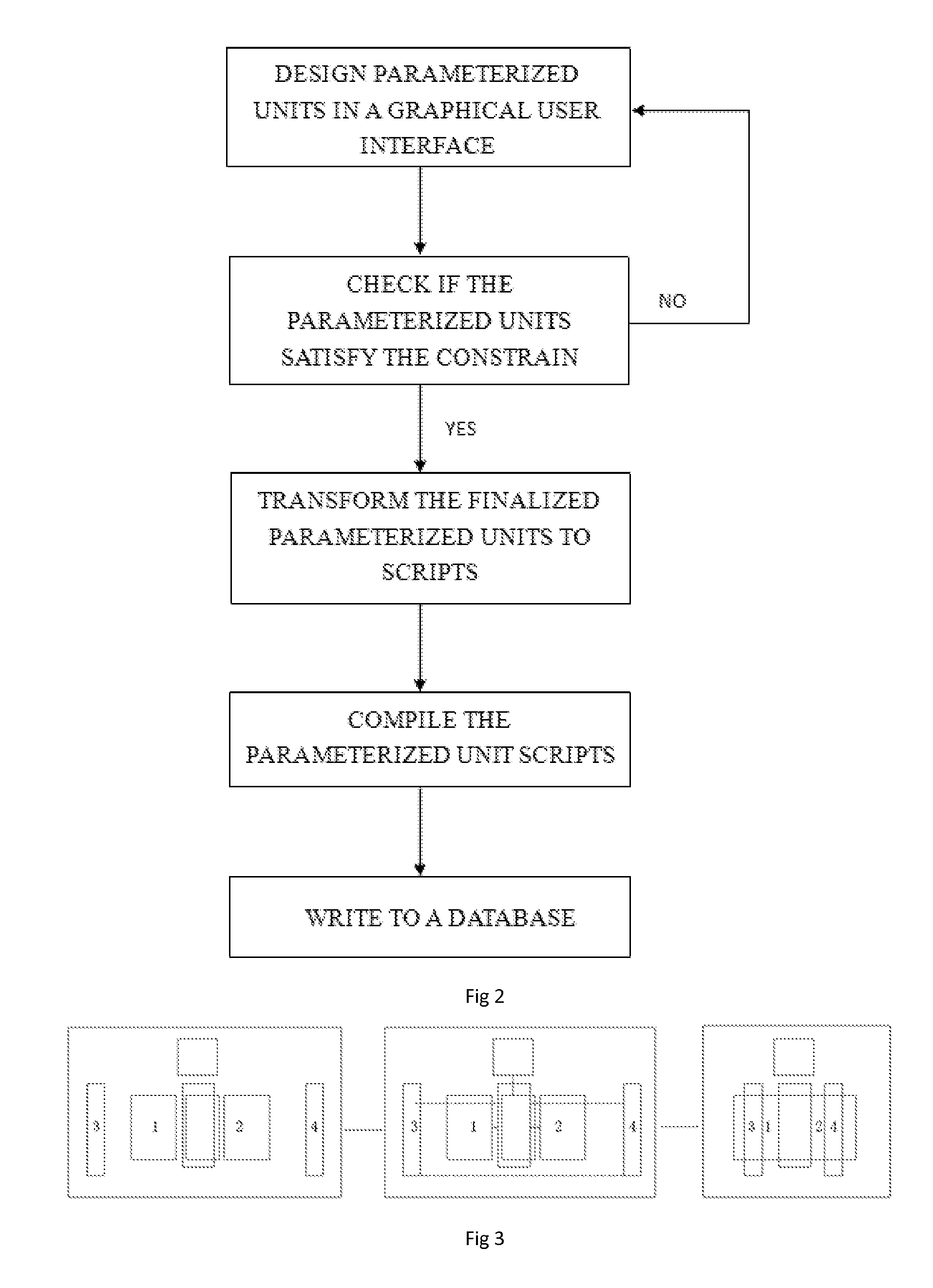
[0023]The graphical user interface makes use of layout editing tools; in addition, the parameterized units are geometric shapes. FIG. 3 is the schematic diagram of designing parameterized units in a graphical user interface of the present invention. It should be understood that the invention includes the following steps when the constraint relations are distance constraint relations:

[0024]Creating two rectangles 1 and 2 in a graphical user interface, and defining the initial value of the distance of their rectangular sides as zero. FIG. 5 is a schematic diagram of using distance constraint relations operation of the present invention. As shown in FIG. 5, the distance between two rectangles is zero under the distance constraint relations.

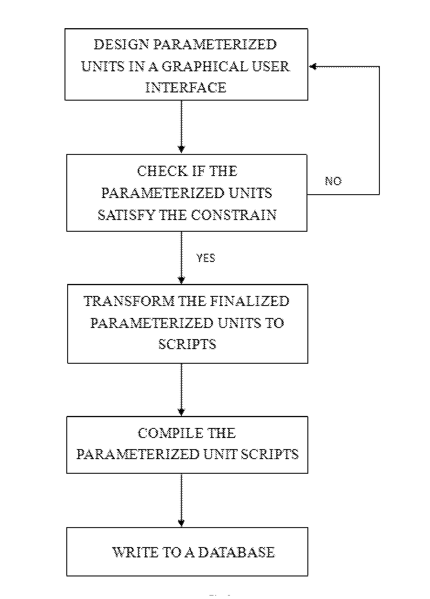
[0025]Transforming the finalized parameterized units to scripts. The transformation process is shown in FIG. 4, it includes: first, analyzing the geometries of parameterized units and correspo...

example 2

The Constraint Relations are Alignment Constraint Relations

[0027]The graphical user interface makes use of layout editing tools; in addition, the parameterized units are geometric shapes. FIG. 3 is the schematic diagram of designing parameterized units in a graphical user interface of the present invention. It should be understood that the invention includes the following steps when the constraint relations are alignment constraint relations:

[0028](1) Creating two rectangles 3 and 4 in a graphical user interface, and defining the centers of the two rectangular sides in an alignment constraint relation in the vertical direction. FIG. 6 is a schematic diagram of using alignment constraint relations operation of the present invention. In FIG. 6, the two rectangles are defined where the centers of corresponding rectangular sides are aligned through the said constraint relation.

[0029](2) Transforming the finalized parameterized units to scripts. The transformation process is shown in FIG...


PUM


Abstract

The present invention relates to a method of method of generating parameterized integrated circuit units in a plurality of platforms. The said method comprising: (1) designing parameterized units in a graphic user interface and defining their constrain relations; (2) transforming the parameterized units to scripts. The invention providing a method of designing parameterized units in a graphical user interface without editing parameterized unit scripts, reducing the complexity of the design process and the design cycle; in addition, it is very easy for users to design and maintenance; at the same time, increasing the portability.

Description

CROSS REFERENCE TO RELATED PATENT APPLICATION[0001]The present application claims the priority of the Chinese patent application No. 201210401119.0 filed on Oct. 22, 2012, which application is incorporated herein by referenceFIELD OF THE INVENTION[0002]The present invention relates generally to the field of designing and manufacturing semiconductors, and more specifically, to a method of generating parameterized integrated circuit units in a plurality of platforms.BACKGROUND OF THE INVENTION[0003]Parameterized units need to be designed in the process of designing and manufacturing integrated circuit chips. For example, the semiconductor manufacturer will provide to the design company process development kit (PDK), and there are many parameterized units in the PDK that will be called to meet different needs when the design company designs a chip. In addition, semiconductor manufacturers use parameterized units to generate large numbers of test patterns and test circuits quickly for y...

Claims


Application Information

Patent Timeline
Patent Type & Authority Applications(United States)
IPC IPC(8): G06F17/50
CPCG06F17/5081G06F30/00G06F2111/04
Inventor ZHENG, YONGJUN
Owner SEMITRONIX
Why Eureka
Try Eureka