Unlock instant, AI-driven research and patent intelligence for your innovation.

Debugging fixture

A jig, universal serial bus technology, applied in the direction of response error generation, program control design, instrumentation, etc.

Inactive Publication Date: 2014-08-27
SKYMEDI CORPORATION
View PDF3 Cites 0 Cited by
  • Summary
  • Abstract
  • Description
  • Claims
  • Application Information

AI Technical Summary

Problems solved by technology

As a result, additional time is often required to repackage the product after the problem is resolved

Method used


Image

  • Debugging fixture
  • Debugging fixture
  • Debugging fixture

Examples


Embodiment Construction

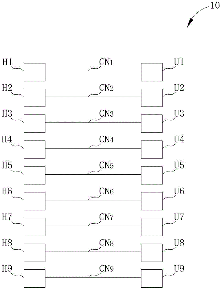
[0017] Please refer to figure 1 , figure 1 It is a schematic diagram of a jig 10 according to an embodiment of the present invention. The jig 10 is used to control a USB device to perform normal, format or debug operations. like figure 1 As shown, the jig 10 includes connectors CN1 - CN9 and signal pins H1 - H9 and U1 - U9 . The signal pins H1-H9 are correspondingly located at the ends of the connectors CN1-CN9, and are used to connect to a host device. The signal pins U1-U9 are correspondingly located at the other end of the connectors CN1-CN9, and are used to connect to the USB device. Therefore, the signal pins H1-H9 and U1-U9 can transmit signals between the host device and the USB device.

[0018] Please refer to FIG. 2 and FIG. 3 . FIG. 2 and FIG. 3 are schematic diagrams of the operation of the jig 10 . As shown in FIG. 2 , the jig 10 operates in the third-generation USB mode. In detail, the signal pins H5, H6 and U5, U6 are correspondingly connected with the pin...


PUM


Abstract

A fixture, for connecting a host device and a universal serial bus (USB) device, the fixture comprises a plurality of connectors; a plurality of first signal pins, located at first ends of the plurality of connectors for connecting to the host device; and a plurality of second signal pins, located at second ends of the plurality of connectors for connecting to the USB device; wherein a first part of the plurality of connectors are used for transmitting signals between the host device and the USB device in a USB mode; wherein a second part of the plurality of connectors are retained in a specified state for providing a control signal to control the USB device to enter an operating mode.

Description

technical field [0001] The present invention relates to a debugging fixture, in particular to a debugging fixture used to control a universal serial bus device to perform formatting or debugging operations. Background technique [0002] With the advancement of technology, manufacturers are committed to developing new products to enhance market competitiveness. Therefore, manufacturers strive to increase product development and debugging speed to increase market visibility of new products. [0003] Typically, manufacturers perform complex tests to confirm that a product is functioning properly. When a problem occurs, the manufacturer must remove or even destroy the product casing to perform debugging operations. As a result, additional time is often required to repackage the product after the problem has been resolved. Due to the complex and delicate appearance of the product, how to speed up the debugging operation and avoid damaging the product has become one of the goal...

Claims


Application Information

Patent Timeline
Patent Type & Authority Applications(China)
IPC IPC(8): G06F13/40G06F11/07
CPCG06F13/00G06F2213/0042G06F9/4413G06F13/4068
Inventor 萧博文陈鼎允
Owner SKYMEDI CORPORATION