
Extrusion head and method for producing hollow bodies

A head and extruder technology, which is applied in applications, household appliances, household components, etc., can solve the problems of complicated and expensive wall thickness control system technology

Inactive Publication Date: 2014-08-27
海因茨·格罗斯
View PDF10 Cites 2 Cited by
  • Summary
  • Abstract
  • Description
  • Claims
  • Application Information

AI Technical Summary

Problems solved by technology

Such a dynamic radial wall thickness control system, as proposed in DE 2654001, DE 19931870 or EP 1 685 943 B1, is now, as already stated, technically very complex and correspondingly very expensive

Method used


Image

  • Extrusion head and method for producing hollow bodies
  • Extrusion head and method for producing hollow bodies
  • Extrusion head and method for producing hollow bodies

Examples


Embodiment Construction

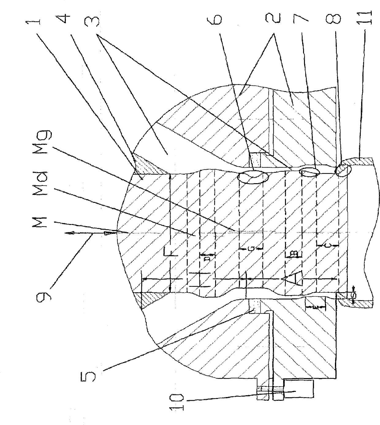
[0033] as in figure 1 As shown in , the extrusion head has a first head part, namely the blowing needle 1 , and a second head part, namely the nozzle 2 which defines the flow channel 3 . The head geometry or the shape of the annular flow channel 3 between the nozzle and the blowing needle can, as usual, be almost circular, with the blowing needle 1 positioned centrally in the nozzle 2 . The blowing needle 1 and the nozzle 2 thus have the same center line M. Of course, the nozzle 2 and / or the blowing needle 1 can also have any other geometric shape, for example a square, rectangular, oval geometry or also other point-symmetrical geometries.

[0034] Nozzle 2 is fixed with figure 1 The extruder connection is not shown, while the blowing needle 1 can move relative to the fixed nozzle 2 . In the outlet area A of the head, the blowing needle 1 and the nozzle 2 each have at least one head section which has a constant cross-section within the head section. The blowing needle 1 ha...


PUM


Abstract

The invention relates to an extrusion head and to a method, by way of which for example the thickness distribution of hollow bodies can be further improved. To this end, the extrusion head consists of at least one mandrel (1) and a nozzle (2), which mandrel (1) and nozzle (2) may be geometrically rigid and thus not changeable or else deformable in a regionally flexible manner and which form a flow duct (3), wherein the mandrel (1) and the nozzle (2) are positionally changeable in relation to one another, as a result of which the geometry of an outlet gap (s) of the flow duct (3) is changeable during the discharge of a melt, wherein each head part has at least one head section having a constant cross-sectional area in an outlet region (A) of the extrusion head, and wherein at least one head part has at least two head sections (B) and (C); which each have predominantly constant cross-sectional areas within the head section (B), (C), are axially spaced apart and have different cross-sectional areas from one another.

Description

technical field [0001] The invention relates to an extrusion head for a plastic extrusion machine, in particular for the manufacture of parisons for blow-molded containers, which has two head parts, wherein the first head part is a blow needle and the second The two head parts are nozzles, and wherein the two head parts can be moved relative to each other in the axial direction via the outlet region, whereby the geometry of the outlet gap of the flow channel between blowing needle and nozzle can be changed and thus also It is possible to vary the wall thickness of the hose-like plastic strip that emerges from the head. [0002] In plastic extrusion machines, the extrusion head is used to discharge a flowable plastic melt, so that the plastic can be discharged at the end of the head with a precisely defined geometry and the desired wall thickness or distribution of the wall thickness melt. If hollow profiles such as hoses, pipes or profiles are to be produced from a plastic m...

Claims


Application Information

Patent Timeline
Patent Type & Authority Applications(China)
IPC IPC(8): B29C47/22B29C47/92B29C49/04B29C47/08B29C48/325B29C48/92
CPCB29C47/0054B29L2031/712B29C47/22B29L2023/00B29C47/225B29C2947/92904B29C2947/92647B29K2101/00B29C47/0852B29C47/0057B29C49/04B29C47/92B29C47/0023B29C48/92B29C48/0017B29C48/09B29C48/327B29C48/0018B29C2948/92647B29C48/3003B29C2948/92904B29C48/30B29C48/325B29C49/04116
Inventor 海因茨.格罗斯
Owner 海因茨·格罗斯
Learn More