A waste heat treatment impurity feeding control system

A control system and impurity technology, applied in the field of waste heat treatment impurity blanking control system, can solve problems such as unpleasant odor, temperature loss in furnace, impurity accumulation, etc., and achieve easy control of impurity discharge, full energy utilization, and impurity removal speed. uniform effect

Inactive Publication Date: 2017-11-03
SINOBIOWAY BIOENVIRONMENT CO LTD
View PDF6 Cites 0 Cited by
  • Summary
  • Abstract
  • Description
  • Claims
  • Application Information

AI Technical Summary

Problems solved by technology

[0002] At present, most of the garbage disposal methods in our country are landfills. Because domestic garbage in our country has the characteristics of low calorific value and high water content, landfills are used to dispose of garbage. In addition to the unpleasant smell produced during the landfill process, the leachate produced It is a difficult problem of landfill technology. The generation of leachate seriously pollutes groundwater and endangers human survival.
[0003] The heat treatment method is relatively easy to deal with heat treatment products that pollute the environment. In the process of heat treatment of waste, it is necessary to discharge the impurities after heat treatment. However, if the amount of impurities discharged is too large, the temperature in the furnace will be greatly lost, resulting in energy waste. , and too little discharge of impurities will cause accumulation of impurities, which will affect the effect of heat treatment of waste, and the impurities will be unevenly distributed in the storage device after discharge

Method used


Image

  • A waste heat treatment impurity feeding control system

Examples


Embodiment Construction

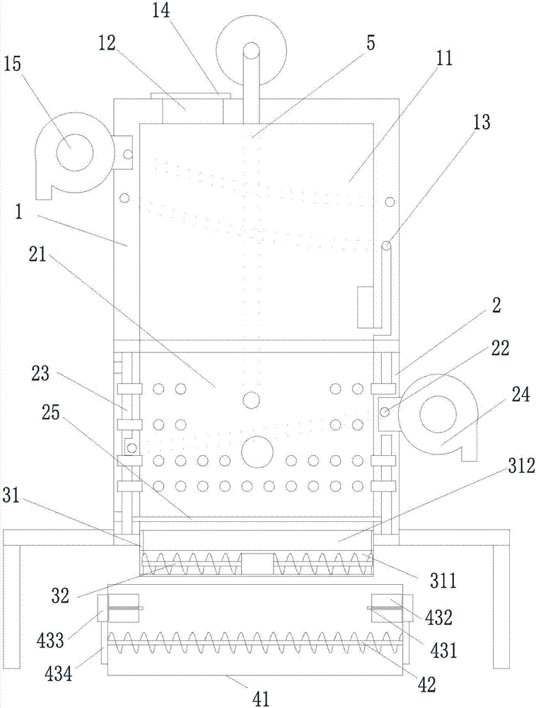
[0020] refer to figure 1 As shown, a waste heat treatment impurity discharge control system proposed by the present invention includes an upper furnace body 1 , a lower furnace body 2 , an impurity removal mechanism, an impurity recovery mechanism, a control mechanism and an air duct 5 .

[0021] The upper furnace body 1 is installed above the lower furnace body 2. The upper furnace body 1 has a miscellaneous storage chamber 11. The upper furnace body 1 is provided with a feed through hole 12 and an air outlet through hole 13 connected to the miscellaneous storage chamber 11. The upper furnace body 1 A feed door 14 is installed corresponding to the position of the feed through hole 12, and a first blower 15 is installed on the upper furnace body 1, and the air inlet of the first blower 15 communicates with the air outlet through hole 13; the lower furnace body 2 has a heat treatment chamber 21, The heat treatment chamber 21 communicates with the miscellaneous storage chamber 1...


PUM


Abstract

The invention provides a discharging control system for impurities of heat treatment of garbage. The system comprises an upper furnace body, a lower furnace body, an impurity discharging mechanism, an impurity recovering mechanism and a control mechanism, wherein the upper furnace body is mounted on the lower furnace body and comprises an impurity storage cavity, a feeding through hole and an air outlet through hole are formed in the upper furnace body, and a feeding door and a first air blower are mounted on the upper furnace body; a heat treatment cavity is formed in the lower furnace body, an air inlet through hole, a liquid inlet through hole and a liquid outlet through hole are formed in the lower furnace body, a liquid guiding cavity is formed in the furnace wall of the lower furnace body, and a second air blower is mounted on the lower furnace body; the impurity discharging mechanism comprises an impurity discharging frame and two first screw rods, and an impurity discharging through hole and an impurity guiding through hole are formed in the impurity discharging frame; the impurity recovering mechanism comprises an impurity storage box and a second screw rod; the control mechanism comprises a control device and an air pressure sensor. The system is convenient to use, energy is fully utilized, the impurity discharging amount is easy to control, and impurities are evenly distributed after being discharged.

Description

technical field [0001] The invention relates to the field of environmental protection, in particular to a waste heat treatment impurity discharge control system. Background technique [0002] At present, most of the garbage disposal methods in our country are landfills. Because domestic garbage in our country has the characteristics of low calorific value and high water content, landfills are used to dispose of garbage. In addition to the unpleasant smell produced during the landfill process, the leachate produced It is a difficult problem of landfill technology. The generation of leachate seriously pollutes groundwater and endangers human survival. [0003] The heat treatment method is relatively easy to deal with heat treatment products that pollute the environment. In the process of waste heat treatment, the impurities after heat treatment need to be discharged. However, if the amount of impurities discharged is too large, the temperature in the furnace will be greatly lo...

Claims


Application Information

Patent Timeline
Patent Type & Authority Patents(China)
IPC IPC(8): F23G5/50
CPCF23G5/50
Inventor 李启仁曹文波明永刚
Owner SINOBIOWAY BIOENVIRONMENT CO LTD
Why Eureka
Try Eureka