Energy tank and working method thereof

A working method and energy technology, which is applied in the direction of liquid variable capacity machinery, variable capacity pump components, machines/engines, etc., can solve the problems of energy tank temperature rise, explosion, etc., to avoid explosion, ensure safety, and facilitate operation Effect

Inactive Publication Date: 2014-09-03
佛山市艺祥机械有限公司
View PDF5 Cites 2 Cited by
  • Summary
  • Abstract
  • Description
  • Claims
  • Application Information

AI Technical Summary

Problems solved by technology

[0004] In order to solve the above technical problems, the present invention provides an energy tank. The top of the energy tank is set as an air inlet, and the bottom is set as an air outlet, and a compressor is connected to the air outlet. When the compressor works, the air in the energy tank will be quickly Pull it out, so that the energy tank is in a vacuum state. In this way, the temperature of the energy tank will rise due to the friction between the side wall of the energy tank and the air. An atomizing nozzle is installed on the inner wall of the energy tank. The atomized nozzle makes the atomized nozzle spray atomized water into the energy tank, and the atomized water can cool down the energy tank, avoiding the explosion of the energy tank due to excessive temperature, and ensuring the normal operation of the compressor and the energy tank

Method used


Image

  • Energy tank and working method thereof

Examples


Embodiment Construction

[0012] The technical solution and structure of the present invention will be described below in conjunction with the accompanying drawings, so as to facilitate the understanding of those skilled in the art.

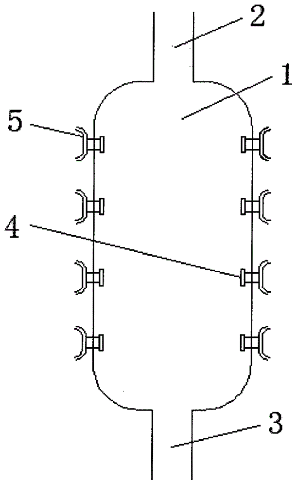
[0013] Such as figure 1 As shown, an energy tank includes a tank body 1 connected with a compressor, the top of the tank body 1 is provided with an air inlet 2, the bottom of the tank body 1 is provided with an air outlet 3, and the air outlet 3 Connected to the compressor, the side wall of the tank body 1 is provided with an atomizing nozzle 4, one end of the atomizing nozzle 4 provided with a nozzle is arranged inside the tank body 1, and the other end is connected to the water inlet pipe 5 outside the tank body 1 .

[0014] The tank body 1 is cylindrical, and the side of the cylindrical tank body 1 is provided with four layers of atomizing nozzles 4 from top to bottom, and each layer of atomizing nozzles includes three atomizing nozzles. The angle between the nozzles...


PUM


Abstract

The invention provides a vacuum energy tank used on a compressor. The energy tank comprises a tank body, wherein the compressor is connected to the tank body; an air inlet is formed in the top of the tank body, and an air outlet is formed in the bottom of the tank body and connected with the compressor; an atomization spray head is arranged on the side wall of the tank body, one end, provided with a nozzle, of the atomization spray head is arranged in the tank body, and the other end of the atomization spray head is connected with a water inlet pipe at the outer part of the tank body. The energy tank can be subjected to cooling process in time in the operation process of the compressor so as to avoid explosion of the energy tank due to excess temperature, and the safety of the energy tank and the compressor is ensured.

Description

technical field [0001] The invention belongs to the field of compressors, and more specifically relates to the field of a compressor or a vacuum energy tank used on it. Background technique [0002] When the compressor is working, it can quickly draw out the air in the energy tank connected to the compressor, so that the energy tank is in a vacuum state, and at the same time, the temperature of the energy tank will rise, and when the compressor and the energy tank are at high temperature When working in this state, the risk of explosion is very easy to occur, which requires timely cooling of the energy tank. However, in the existing technology, there is no device or method that can quickly and easily cool down the energy tank. This greatly restricts the working efficiency of the compressor and energy tank and reduces their service life. Contents of the invention [0003] The technical problem to be solved by the present invention is to provide a method that can quickly an...

Claims


Application Information

Patent Timeline
Patent Type & Authority Applications(China)
IPC IPC(8): F04B39/06
Inventor 陈华陈礼勇陈静陈婷陈礼所陈礼卫陈礼城
Owner 佛山市艺祥机械有限公司
Why Eureka
Try Eureka