
Power line frequency detector

A line frequency and detector technology, applied in frequency measurement devices, frequency to amplitude conversion, instruments, etc., can solve problems such as lighting equipment failure, line frequency change sensitivity, etc.

Active Publication Date: 2014-09-03
DIALOG SEMICON INC CAMPBELL
View PDF8 Cites 3 Cited by
  • Summary
  • Abstract
  • Description
  • Claims
  • Application Information

AI Technical Summary

Problems solved by technology

[0005] A disadvantage of these types of dimmable solid-state lighting devices is that they are sensitive to changes in line frequency
Changes in line frequency can cause significant malfunctions in lighting fixtures if the controller is unable to detect the change in frequency and adjust accordingly when generating the output voltage

Method used


Image

  • Power line frequency detector
  • Power line frequency detector
  • Power line frequency detector

Examples


Embodiment Construction

[0016] The drawings and the following description relate to preferred embodiments of the invention by way of illustration only. It should be noted that, as will be readily appreciated from the following discussion, alternative embodiments of the structures and methods disclosed herein are feasible alternatives that may be implemented without departing from the principles of the claimed invention.

[0017] Reference will now be made in detail to several embodiments of the invention, examples of which are illustrated in the accompanying drawings. Note that similar or identical reference numerals may be used anywhere applicable in the drawings and indicate similar or identical functions. Embodiments of the present invention are depicted for purposes of illustration only. Those skilled in the art will readily appreciate from the following description that alternative embodiments of the structures and methods disclosed herein may be practiced without departing from the principles ...


PUM


Abstract

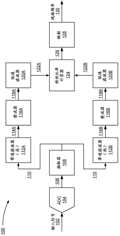
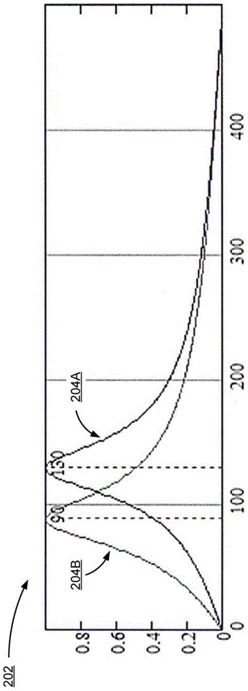
The invention provides a line frequency detector. The line frequency detector receives an input signal representing a power source and detects a line frequency of the power source based on the input signal. The line frequency detector includes a first band pass filter having a pass band centered at an upper end of an expected frequency range of the power source and a second band pass filter having a pass band centered at a lower end of the expected frequency range. The input signal is filtered by the first and second band pass filters, generating a first characteristic signal and a second characteristic signal. The line frequency detector determines a characteristic ratio between the first characteristic signal and the second characteristic signal, and maps the characteristic ratio to the line frequency of the power source.

Description

[0001] Cross References to Related Applications [0002] This application claims the benefit of US Provisional Application Nos. 61 / 769,122, filed February 25, 2013 and 14 / 188,610, filed February 24, 2014, which are hereby incorporated by reference in their entireties. Background technique [0003] The present disclosure relates to line frequency detectors, and in particular to detecting the line frequency of a power supply for dimmable solid state lighting. [0004] Solid state lighting can be connected to a wall dimmer to provide the user with a method of varying the brightness of the lighting. Wall dimmers typically receive power as a sinusoidal waveform (eg, 50Hz or 60Hz line frequency AC power) and perform phase cutting on the waveform to generate an input voltage for the lighting fixture. A controller in a solid state lighting device measures the phase angle of the phase cut and causes a driver circuit to generate an output current at a corresponding power level of a so...

Claims


Application Information

Patent Timeline
IPC IPC(8): G01R23/02
CPCG01R23/06G01R23/14G01R19/2513
Inventor J·W·科斯特森
Owner DIALOG SEMICON INC CAMPBELL
Learn More