Static state calibration device and method for machine visual surface detection equipment

A static calibration and surface detection technology, applied in the field of measurement, can solve the problems of roughly observing the imaging effect of the camera, the difficulty of precise adjustment of the camera, and the lack of matching adjustment devices and methods for the light source and the camera, so as to achieve the effect of ensuring the calibration accuracy

Active Publication Date: 2014-09-03
BAOSHAN IRON & STEEL CO LTD
View PDF9 Cites 32 Cited by
  • Summary
  • Abstract
  • Description
  • Claims
  • Application Information

AI Technical Summary

Problems solved by technology

[0012] The above two technical solutions can only roughly observe the imaging effect of the camera, and there is no matching adjustment device and method for the light source and the camera, so it is very difficult to achieve precise adjustment of the camera

Method used


Image

  • Static state calibration device and method for machine visual surface detection equipment
  • Static state calibration device and method for machine visual surface detection equipment
  • Static state calibration device and method for machine visual surface detection equipment

Examples


Embodiment approach 1

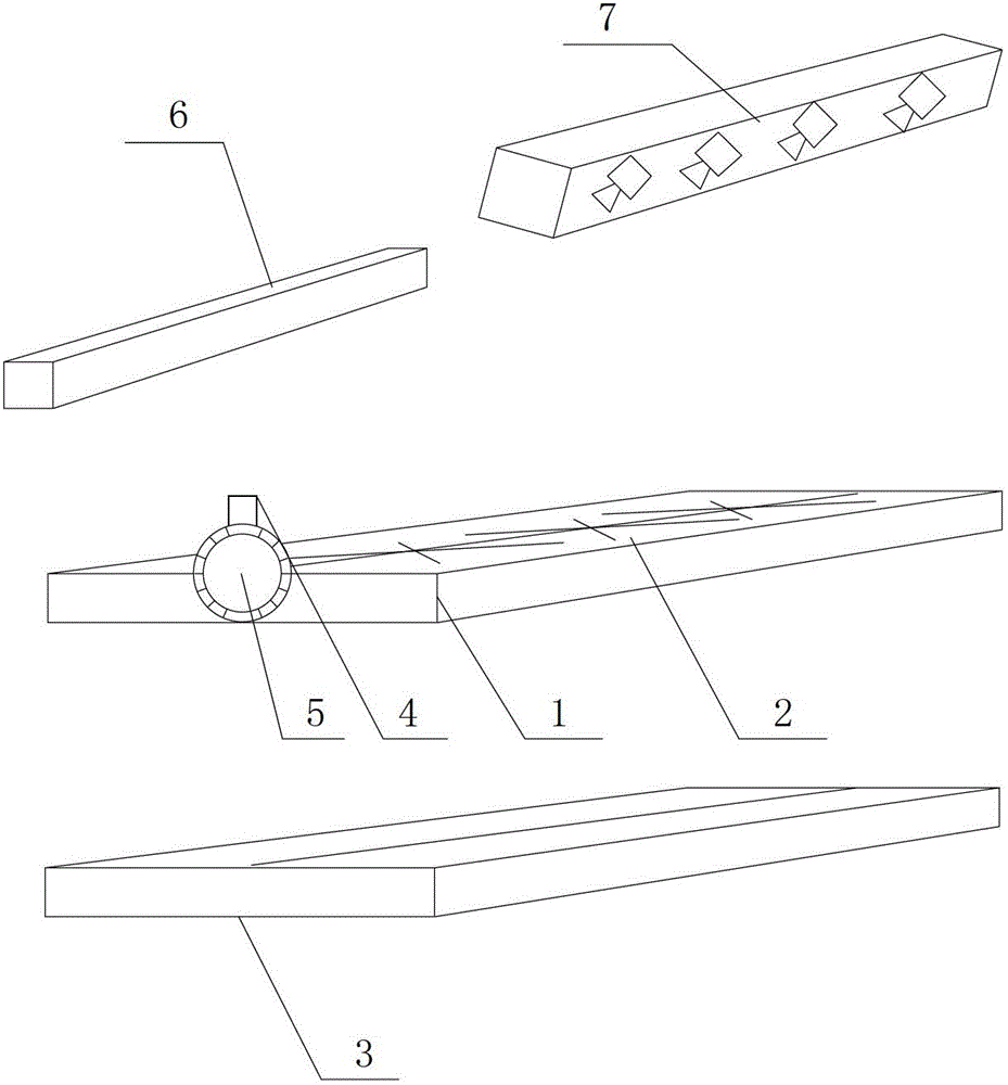
[0083] Such as Figure 4 , Figure 5 As shown, align the center line of the ruler 1 with the imaging position of the selected collected sample and put it in place. According to the previously designed imaging angle of the light source, adjust the angle adjustment device 5 to reach the preset angle, turn on the laser emitter 4, and the emitter will emit Create a parallel laser line, adjust the light source according to the pre-designed height of the light source and make the center position of the light source coincide with the laser line, adjust the level, and complete the determination of the angular position of the light source.

[0084] The determination of the angular position of the camera box is consistent with the light source method.

[0085] After the angle adjustment, the matching imaging between the light source and the camera is basically achieved. In order to further adjust the camera imaging effect, the three movable calibration modules 2 on the scale 1 are resp...

Embodiment approach 2

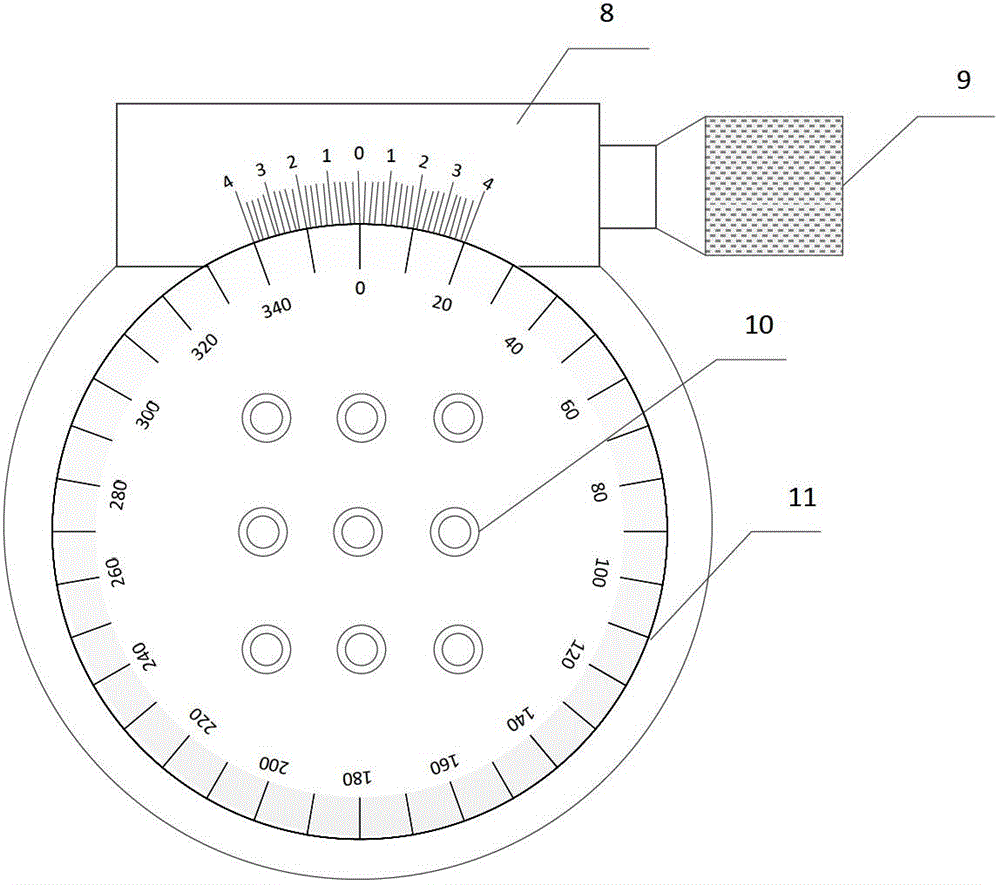
[0087] The device of this patent invention can be used to calibrate the calibration problem when multiple cameras are used together, that is, to adjust the collinear problem of the imaging positions of multiple cameras. Such as Figure 8 As shown, the length of the ruler is appropriately extended according to the field imaging width, and the position of the calibration module is adjusted so that it is located at the head, tail and middle of a camera respectively, and the real-time images collected by two adjacent cameras are respectively observed. The degree and number of thick and thin solid lines can determine whether the camera imaging is on the same straight line, and properly adjust the micro-angle of the camera to achieve the purpose of multiple cameras collinear.

[0088]The implementation of the technical solution of the present invention can accurately locate the imaging position of the light source and the camera, and quickly and accurately adjust the micro-angle of ...


PUM


Abstract

A static state calibration device and method for machine visual surface detection equipment belongs to the measuring field; the static state calibration device comprises a scale, a movable calibration module, an expandable scale, a laser emitter and an angle regulator; the static state calibration device can accurately position a light source and a camera imaging position; the calibration module can fast and accurately adjust a micro angle of a linear array camera so as to ensure imaging accuracy and consistency, is suitable for adjustment between one linear array camera and the light source, and suitable for adjustment between a plurality of cameras and the light source; the static state calibration device is suitable for lab equipment calibration, and suitable for field equipment calibration and adjustment; the static state calibration device can directly check acquisition image effect so as to ensure whether the camera is adjusted to a best position or not, thereby improving system detection accuracy, and improving debug work efficiency; the static state calibration device can be widely applied in calibration or management field of one or more linear array cameras.

Description

technical field [0001] The invention belongs to the field of measurement, and in particular relates to a calibration / marking device and method for machine vision surface detection equipment. Background technique [0002] The strip surface defect detection system based on machine vision has been widely used in major iron and steel enterprises in the world. This kind of inspection system usually consists of multiple CCD cameras covering the entire width direction of the strip, and acquires images of the surface of the strip, and then draws inspection conclusions by analyzing the image data. [0003] Machine vision inspection technology, divided from the technical level, can be divided into two main technical links, image acquisition, image analysis and recognition. Among them, image acquisition is the basis of the vision system and the key to the successful design of the vision system. At the same time, obtaining high-quality image input will greatly improve the efficiency o...

Claims


Application Information

Patent Timeline
Patent Type & Authority Applications(China)
IPC IPC(8): G06T7/00G01N21/88
Inventor 梁爽何永辉杨水山彭铁根石桂芬宗德祥
Owner BAOSHAN IRON & STEEL CO LTD
Why Eureka
Try Eureka