Camera calibration device based on diffractive optical element

A diffractive optical element and camera calibration technology, which is applied in the field of photogrammetry, can solve the problems of large space occupation, high cost, and large space required for arranging the control field, and achieve the effects of ensuring calibration accuracy, saving space and cost

Inactive Publication Date: 2018-03-23
CHANGGUANG SATELLITE TECH CO LTD
View PDF4 Cites 9 Cited by
  • Summary
  • Abstract
  • Description
  • Claims
  • Application Information

AI Technical Summary

Problems solved by technology

This method can be applied to any camera model and has high calibration accuracy, but it takes a large space to arrange the control field, and enough control points with known spatial coordinates are arranged according to the accuracy requirements
[0005] Traditional camera calibration methods require large and expensive instruments and equipment or arrange large indoor and outdoor calibration fields, all of which have the problems of large space occupation and high cost

Method used


Image

  • Camera calibration device based on diffractive optical element
  • Camera calibration device based on diffractive optical element

Examples


Embodiment Construction

[0022] The present invention will be described in further detail below in conjunction with the accompanying drawings and embodiments.

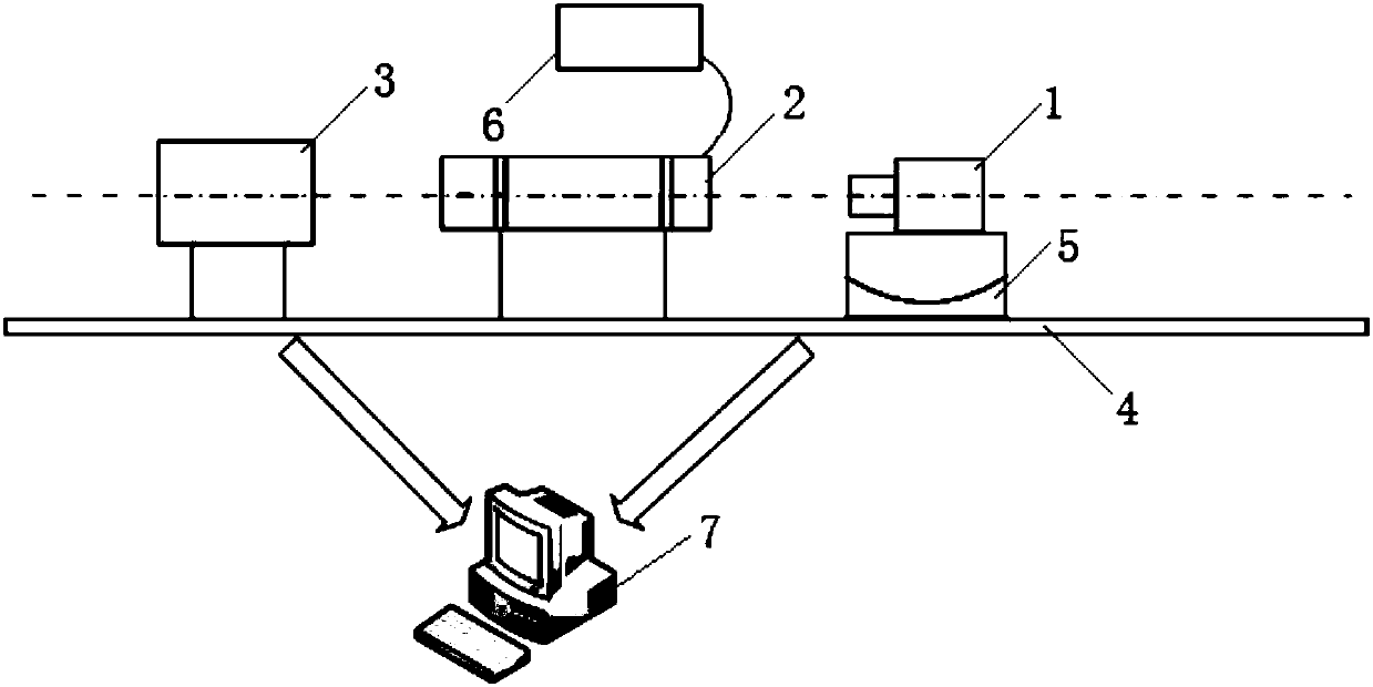
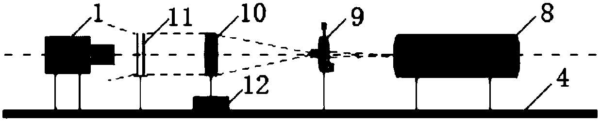
[0023] A camera calibration device based on a diffractive optical element, comprising: a laser 8, a spatial filter 9, a collimator 10, and a double-crossed one-dimensional DOE11; the beam emitted by the laser 8 is vertically incident on the spatial filter 9 and the collimator in turn 10 and double-crossed one-dimensional DOE11.

[0024] The layout diagram of a camera calibration device based on diffractive optical elements of the present invention can be found in figure 1 , using DOE to build an optical calibration platform. In this embodiment, the laser 8, the spatial filter 9, the collimating mirror 10, and the double-crossed one-dimensional DOE 11 are sequentially arranged along the same axis, and all devices are installed and fixed on the same line of holes on the optical table 4, along the same The axis arrangement simplifies the elemen...


PUM


Abstract

The invention discloses a camera calibration device based on a diffractive optical element, relates to the field of photogrammetry, and solves the problems of high cost and large space occupied by existing calibration devices. The device includes a laser, a spatial filter, a collimating lens, and a double-crossed one-dimensional DOE. The laser, the spatial filter, the collimating lens and the double-crossed one-dimensional DOE are sequentially arranged along the same axis, and a laser beam emitted from the laser is incident perpendicularly to the spatial filter, the collimating lens and the double-crossed one-dimensional DOE sequentially. The camera calibration device in the invention replaces the existing high-cost calibration module that occupies a large space through a diffraction starpoint network composed of N*N star points and obtained using the double-crossed one-dimensional DOE; simulates infinity imaging by using the collimating lens to comply with conditions of the use of anaerial survey camera; and at the same time does not limit the processing algorithm, that is, can guarantee the calibration accuracy. The camera calibration device can be widely used in the field of camera calibration.

Description

technical field [0001] The invention relates to the field of photogrammetry, in particular to a camera calibration device based on diffractive optical elements. Background technique [0002] The existing commonly used camera calibration methods include precision goniometric method and experimental field calibration. Precision goniometric method is a method often used by people in the laboratory for geometric calibration of the inner orientation elements of aerial cameras. figure 1 It is a device diagram of the precision goniometric method. The calibration principle of the precision goniometric method is to rotate the camera 1 to image the star point passing through the collimator 2 . The precision turntable 5, the collimator 2 and the star point plate 3 are sequentially placed on the optical platform 4 along the same horizontal center line, the camera 1 to be tested is placed on the precision turntable 5 and aligned with the collimator 2, and the collimator 2 focuses Place...

Claims


Application Information

Patent Timeline
Patent Type & Authority Applications(China)
IPC IPC(8): G06T7/80
Inventor 屠志鹏贾益李文涛
Owner CHANGGUANG SATELLITE TECH CO LTD
Why Eureka
Try Eureka