
Heat exchanger valve arrangement

A technology for heat exchanger valves and heat exchangers, applied in the direction of valve devices, valve operation/release devices, valve details, etc., can solve complex and expensive problems

Active Publication Date: 2014-09-10
DANFOSS AS
View PDF6 Cites 2 Cited by
  • Summary
  • Abstract
  • Description
  • Claims
  • Application Information

AI Technical Summary

Problems solved by technology

In some cases it is complex and expensive to install both valve arrangements in the heat exchanger arrangement

Method used


Image

  • Heat exchanger valve arrangement
  • Heat exchanger valve arrangement
  • Heat exchanger valve arrangement

Examples


Embodiment Construction

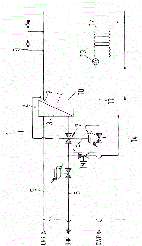
[0020] figure 1 A heat exchanger arrangement 1 is shown in schematic form, which is suitable for a sub-station, for example suitable for use in a house for heating domestic water. However, the heat exchanger arrangement can equally be used in any other system.

[0021] The heat exchanger arrangement 1 comprises a heat exchanger 2 . The heat exchanger 2 comprises a primary side 3 and a secondary side 4 . The main side 3 is connected to a domestic heating supply line 5 which is connected to a domestic heating supply DHS. The main side 3 of the heat exchanger 2 is also connected to a domestic heating return line 6 which is connected to a domestic heating return connection DHR. The first valve device 7 is arranged in the domestic return line 6 . When the first valve device 7 is closed, there is no flow of domestic heating medium through the main side 3 of the heat exchanger 2 .

[0022] The secondary side 4 of the heat exchanger 3 comprises an output 8 connected to one or mor...


PUM


Abstract

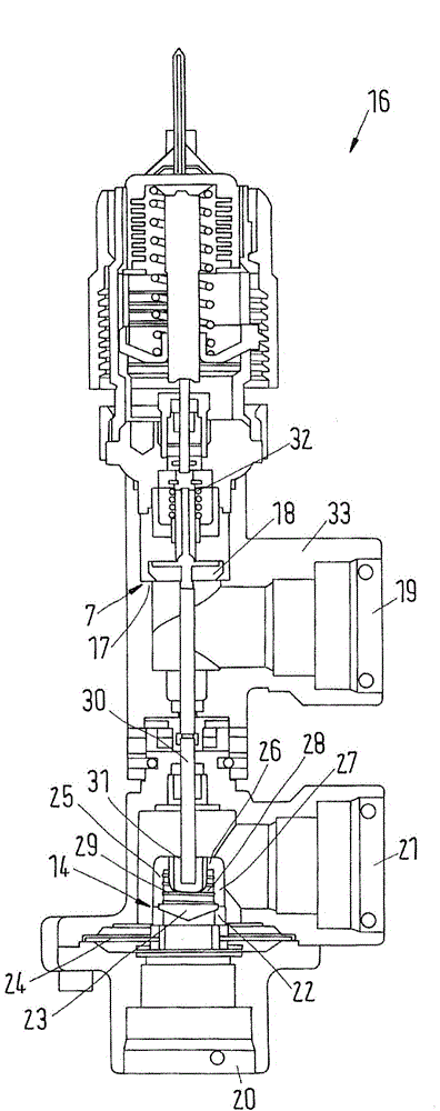
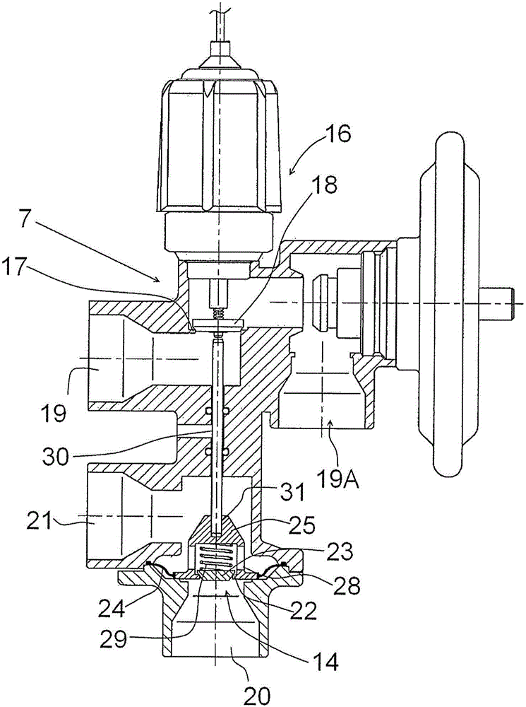
A heat exchanger valve arrangement is provided comprising first valve means (7) to be arranged in a flow line (6) connected to a primary side (3) of a heat exchanger (2) and comprising a first input port (19) and a first output port and a valve seat (17) and an first valve element (18) between said first input port (19) and said first output port, said valve arrangement further comprising second valve (14) means to be arranged in a flow line (11) connected to a secondary side (4) of said heat exchanger (2) and comprising a second input port (20) and a second output port (21) and a second valve seat (22) and a second valve element (23) between said second input port (20) and said second output port (21), characterized in that said first valve means (7) and said second valve means (14) are combined in a common valve unit (16). Such a valve arrangement should be simple to install. To this end said first valve means (7) and said second valve means (14) are combined in a common valve unit (16).

Description

technical field [0001] The invention relates to a heat exchanger valve arrangement comprising a first valve arrangement arranged in a flow line connected to the main side of the heat exchanger and comprising a first input port and a first output port and an arrangement a first valve element and a first valve seat between the first input port and the first output port, the valve arrangement further comprising a second valve arrangement arranged in connection with the heat exchanger The secondary side is connected in the flow line and includes a second input port and a second output port, and a second valve element and a second valve seat arranged between the second input port and the second output port. Background technique [0002] The invention will hereinafter be described in connection with a heat exchanger arrangement provided for supplying domestic hot water to a tap. The water tap is connected to the output of the secondary side of the heat exchanger. The input of th...

Claims


Application Information

Patent Timeline
Patent Type & Authority Applications(China)
IPC IPC(8): F16K11/14F16K31/365
CPCF16K11/044F24D19/1066F24D3/08F16K51/00F16K17/00
Inventor 托马兹·撒加托马兹·维迪兹
Owner DANFOSS AS
Learn More