An aircraft wing large deformation test loading device

A loading device and large deformation technology, which is applied in the direction of measuring devices, machine/structural component testing, instruments, etc., can solve problems such as difficult lifting and installation, large impact loads, and high installation strength, so as to reduce installation workload and coordinate loading , The effect of eliminating potential safety hazards

Active Publication Date: 2016-09-07
CHINA AIRPLANT STRENGTH RES INST
View PDF4 Cites 0 Cited by
  • Summary
  • Abstract
  • Description
  • Claims
  • Application Information

AI Technical Summary

Problems solved by technology

In this loading method, the two actuators are connected in series through a soft type, which is heavy, difficult to lift and install, and not easy to replace; on the other hand, the two loading actuators are controlled by a control module through the load. When the travel of the two actuators is switched, a large impact load will be generated, which will easily lead to the termination of the test protection, the risk of the test, the control is more difficult, and the control accuracy is low; third, under normal circumstances, the distance between the wing and the ground is about 4500 mm , the length of the double-action actuators in series is too long to be installed on the lower surface of the wing, so it can only be changed to upward loading through the steering pulley. Sometimes, individual upward loading points also need to be changed through the steering pulley due to the limited installation space. For downward loading, its mounting strength is considerable

Method used


Image

  • An aircraft wing large deformation test loading device
  • An aircraft wing large deformation test loading device
  • An aircraft wing large deformation test loading device

Examples


Embodiment Construction

[0024] Specific embodiments of the present invention will be further described in detail below.

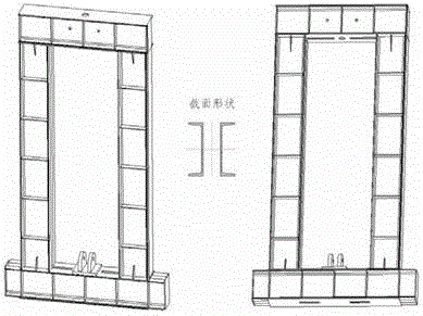
[0025] see figure 2 , The aircraft wing large deformation test loading device of the present invention includes a frame 1, an actuator 2, a rolling wheel 3, a rolling wheel support 4, a starting bolt 5, a steel cable 6, a guide wheel 7, and a movable load-bearing beam 8.

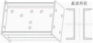
[0026] Wherein, the frame is a rectangular component welded with channel steel, such as image 3 As shown; the two ears at the bottom of the frame are used to install the actuator, and the gap at the bottom can be used to install the frame on the ground or the bearing ceiling through the anchor bolts; the ears of the rolling wheel support extend into the gap on both sides of the frame; the top of the frame Two guide wheels are installed by bolts, square holes and round holes are processed on the top of the frame for winding and passing steel cables.

[0027] Actuator, such as Figure 4 As shown in the figure...


PUM


Abstract

The invention belongs to the aircraft strength test technology, and relates to a loading device under the condition of large deformation of the wing. The loading device of the aircraft wing large deformation test of the present invention comprises a frame, an actuator, a rolling wheel, a rolling wheel support, a starting bolt, a steel cable, a guide wheel, and a movable load-bearing beam. One end of the actuator is connected to the bottom of the frame, and the other end is connected to the movable load-bearing beam. The two rolling wheel bearings are installed on the two ends of the movable load-bearing beam respectively, and the bosses of the rolling wheel bearings extend into the inner surface chute of the adjacent two frames respectively. Four guide wheels and one starting bolt are installed on the movable load-bearing beam, and two guide wheels are installed on the top of the frame; after the earring at one end of the steel cable is connected to the starting bolt, the other end of the steel cable circles in turn Each guide wheel passes through from the top of the frame. The loading device of the present invention has an integral frame structure, which is convenient and safe for test installation, and has high control precision. When loading, the movable load-bearing beam moves flexibly, and the loading is coordinated to meet the loading requirements of large deformation of the wing.

Description

technical field [0001] The invention belongs to the aircraft strength test technology, and relates to a loading device satisfying the large deformation of the wing. Background technique [0002] During the structural strength test of an aircraft, the wing usually deforms upward. When the deformation of the wing tip exceeds 2500 mm, the existing loading device cannot meet the loading requirements. On the one hand, the maximum stroke of the existing actuator is 2500 mm; on the other hand, so far, the maximum deformation of the wing tip has not exceeded 5000 mm. for large deformation. [0003] Wing load application technology in the case of large deformation is a difficult point in the strength test of aircraft structure. At present, there is no ideal loading device that can easily apply the wing load in this case. At present, the most (most effective) loading method is the method of connecting double actuators in series, such as figure 1 As shown; when the test is loaded, t...

Claims


Application Information

Patent Timeline
Patent Type & Authority Patents(China)
IPC IPC(8): G01M99/00
Inventor 臧伟锋张海英许飞
Owner CHINA AIRPLANT STRENGTH RES INST
Why Eureka
Try Eureka