
Soil beam bending test device

A technology of bending test and soil beam, which is applied in the direction of testing material strength by applying a stable bending force, can solve the problems of single function, poor precision, simple test data collection method, etc., and achieve high data measurement accuracy, large selection space, The effect of rate stabilization

Active Publication Date: 2016-05-04
ZHEJIANG UNIV
View PDF6 Cites 0 Cited by
  • Summary
  • Abstract
  • Description
  • Claims
  • Application Information

AI Technical Summary

Problems solved by technology

[0003] However, the testing equipment for soil tensile properties currently developed at home and abroad has the following problems: there are many unit test equipment, and there are few model test equipment; traditional test equipment generally uses stress-controlled loading, which cannot capture the softening characteristics of the soil ;The collection method of test data is simple, and the accuracy is poor; the function is single

Method used


Image

  • Soil beam bending test device
  • Soil beam bending test device
  • Soil beam bending test device

Examples


Embodiment Construction

[0016] The present invention will be described in further detail in conjunction with the accompanying drawings and examples.

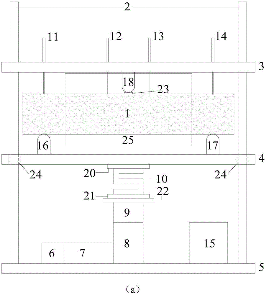
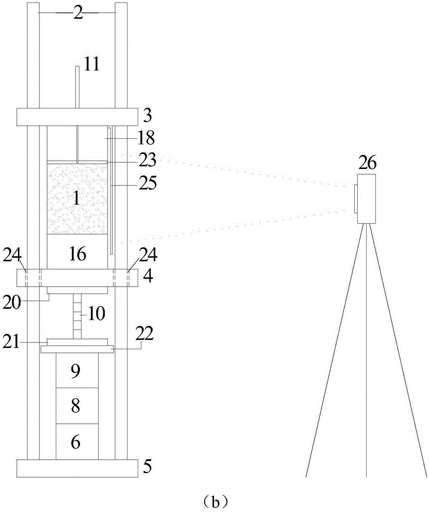
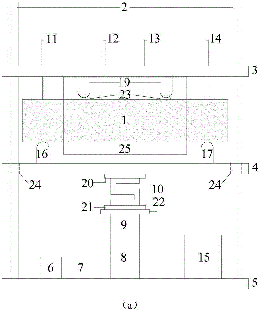
[0017] like Figure 1-2 As shown, a soil beam bending test device of the present invention includes: four steel rods 2, three steel plates 3-5, a servo controller 6, a motor 7, a planetary reducer 8, a ball screw lifter 9, and a force sensor 10 , four displacement sensors 11-14, static data acquisition instrument 15, first support 16, second support 17, three spacers 20-22, plexiglass plate 25, high-definition camera 26;

[0018] Wherein, the bottom ends of the four steel rods 2 are all anchored with the third steel plate 5, the tops of the four steel rods 2 are all anchored with the first steel plate 3, and the second steel plate 4 is located between the first steel plate 3 and the third steel plate 5, The second steel plate 4 is connected with four steel rods 2 through four linear sliders 24; the first support 16 and the second support 17 are fixed ...


PUM


Abstract

The invention discloses a concrete beam flexure testing device. The concrete beam flexure testing device comprises four steel rods, a first steel plate, a second steel plate, a third steel plate, a servo controller, a motor, a planetary reducer, a ball screw lifter, a force sensor, a first displacement sensor, a second displacement sensor, a third displacement sensor, a fourth displacement sensor, a static data acquisition instrument, a first support, a second support, an organic glass panel and a high-definition camera; the concrete beam flexure testing device can be used for performing three-point beam bending testing and four-point beam bending testing; a displacement control loading mode is adopted to achieve stable and controllable speed rate with large choosing range, and the softening character of the concrete beam can be captured; the data acquisition system adopts the force sensor and the displacement sensors to achieve high data measurement precision, and the static data acquisition instrument is utilized to acquire data, so that the concrete beam cracking process can be completely recorded; the high-definition camera is adopted to record the concrete beam crack growth process, accurately observe the strain localization phenomenon and obtain cracking strain.

Description

technical field [0001] The invention belongs to the technical field of mechanical property testing, in particular to a soil beam bending test device. Background technique [0002] Tensile cracks widely exist in cohesive soil layers, such as deformation cracks in clay barriers and clay core walls of earth-rock dams, tension-type ground cracks in loess areas, tensile cracks in soil slopes and foundation pit slope tops, etc. The presence of cracks significantly reduces the impermeability and strength properties of the clay layer. Therefore, it is necessary to study the tensile cracking characteristics of cohesive soil layer from the experimental point of view. [0003] However, the testing equipment for soil tensile properties currently developed at home and abroad has the following problems: there are many unit test equipment, and there are few model test equipment; traditional test equipment generally uses stress-controlled loading, which cannot capture the softening charact...

Claims


Application Information

Patent Timeline
Patent Type & Authority Patents(China)
IPC IPC(8): G01N3/20
Inventor 凌道盛蔡武军徐泽龙卜令方石吉森
Owner ZHEJIANG UNIV
Learn More