Field sequential liquid crystal display driving method and display device
A driving method and technology of liquid crystal display, applied in the direction of static indicators, instruments, etc., can solve problems such as difference in absolute value of data voltage, loss of rotation ability, and liquid crystal not rotating normally.
- Summary
- Abstract
- Description
- Claims
- Application Information
AI Technical Summary
Problems solved by technology
Method used
Image
Examples
Embodiment 1
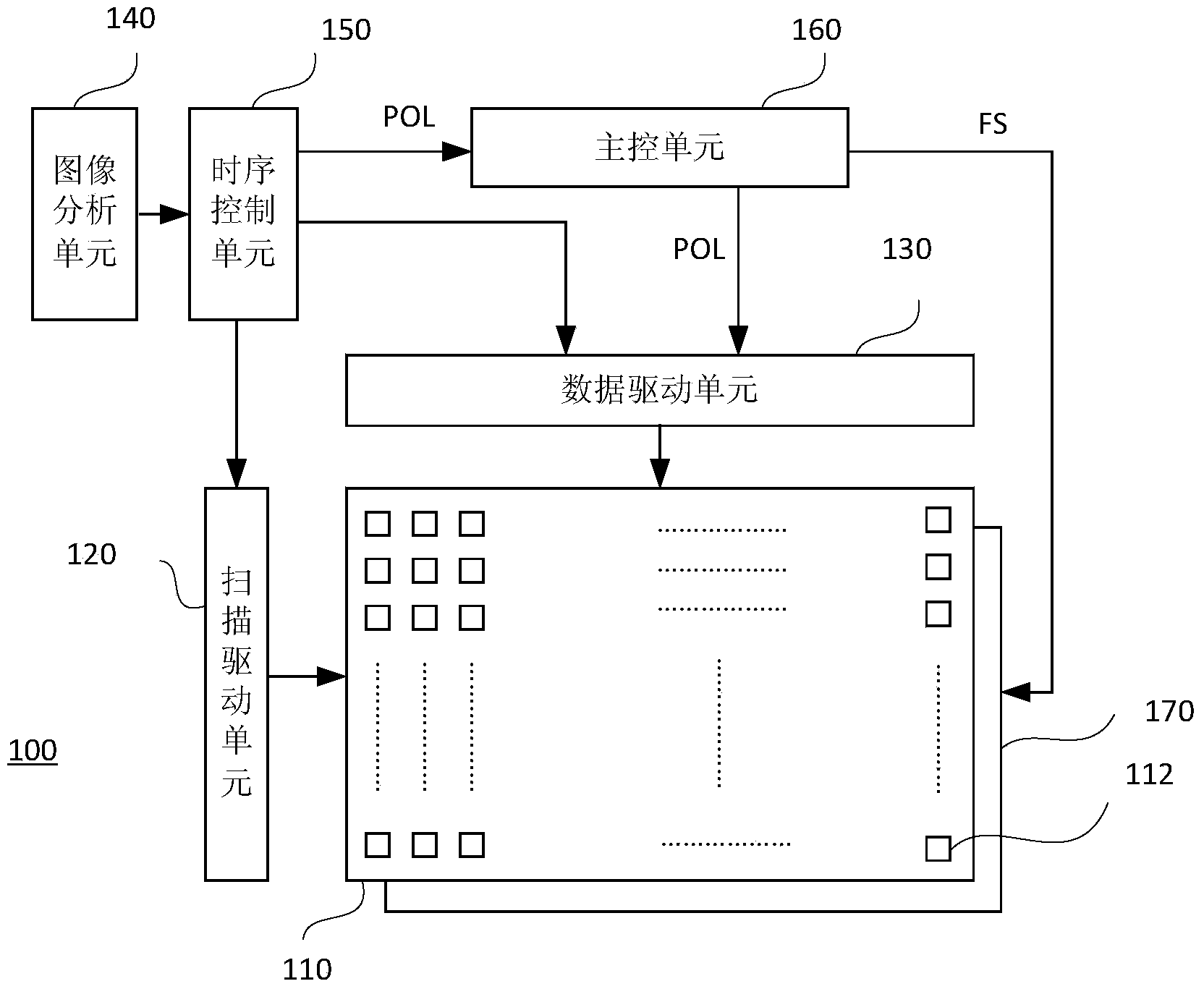
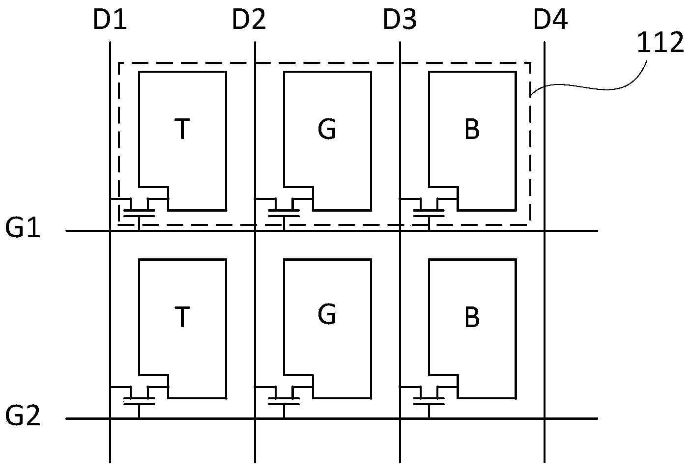
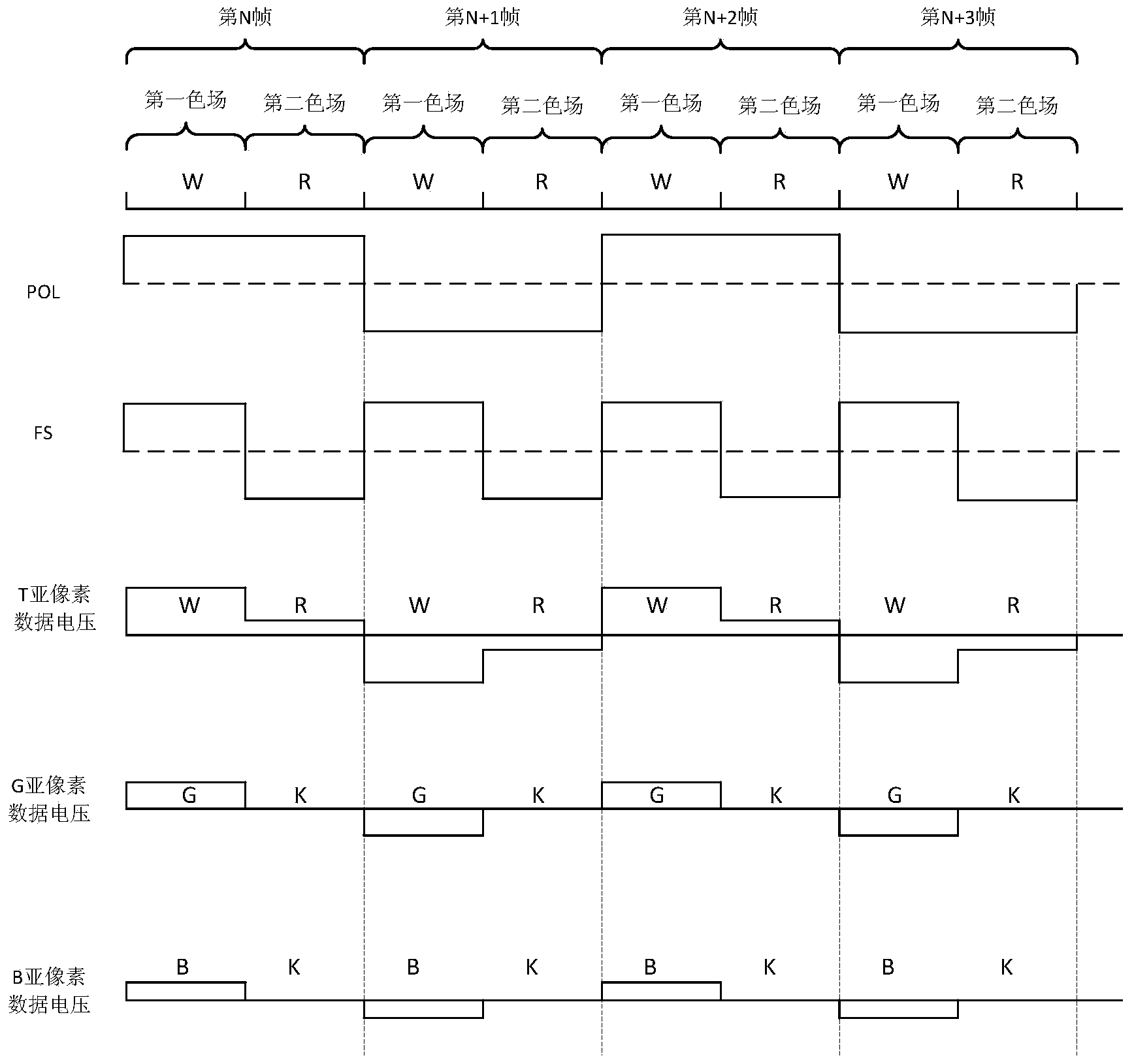
[0036] figure 1 It is a schematic structural diagram of a field sequential liquid crystal display device according to this embodiment. like figure 1 As shown, the liquid crystal display device 100 includes a display panel 110 , a scan driving unit 120 , a data driving unit 130 , an image analysis unit 140 , a timing control unit 150 , a main control unit 160 and a backlight module 170 . The backlight module 170 is disposed at the rear of the display panel 110 to provide a light source for the display panel 110 . The display panel 110 includes a plurality of pixels 112 arranged in a matrix, and each pixel 112 includes a plurality of sub-pixel units. In addition, the backlight module 170 in this embodiment includes a white backlight (W) and a red backlight (R), figure 1 not shown.
[0037] The scan driving unit 120 and the data driving unit 130 are respectively electrically connected to the display panel 110 . The timing control unit 150 is electrically connected to the sca...
Embodiment 2
[0064] This embodiment is basically the same as Embodiment 1. The difference is that, as Figure 5 As shown, the pixel 112 in this embodiment includes two sub-pixel units arranged in parallel, namely a magenta sub-pixel unit (M) and a cyan sub-pixel unit (C). Moreover, the backlight module 170 in this embodiment includes a yellow backlight (Y) and a blue backlight (B).
[0065] Wherein, the yellow backlight passes through the magenta sub-pixel unit (M) to display a red (R) image, and passes through the cyan sub-pixel unit (C) to display a green (G) image. After the blue backlight passes through the magenta sub-pixel unit (M) and the cyan sub-pixel unit (C), a blue image is displayed.
[0066] Therefore, the image analysis unit 140 in this embodiment is used to decompose each frame of image into first image data and second image data. In this embodiment, when the yellow backlight source (Y) emits light, the first part of the data driving signal is provided to multiple sub-pi...
Embodiment 3
[0082] The pixels in the FSC-LCD liquid crystal panel in the prior art usually do not include sub-pixels for color filtering, but provide red, green, and blue color fields through the backlight module and display red, green, and blue in time sequence. Three-color image information. In this embodiment, a driving method is provided to eliminate afterimages.
[0083] Figure 8 is a schematic diagram of the inversion driving method of the FSC-LCD according to this embodiment. The color field sequence signal makes the backlight module generate red, green and blue color fields in one frame period. In the three color fields of the same frame period, the data voltage polarities of the pixels are the same. In the three color fields of adjacent frame periods, the polarities of the data voltages of the pixels are opposite.
[0084] Please refer to Figure 8 , where Vcom is the reference voltage. In the R color field of the Nth frame, the signal voltage Vd on the pixel electrode is ...
PUM
 Abstract
Description
Claims
Application Information
 - R&D
- Intellectual Property
- Life Sciences
- Materials
- Tech Scout
- Unparalleled Data Quality
- Higher Quality Content
- 60% Fewer Hallucinations
Browse by: Latest US Patents, China's latest patents, Technical Efficacy Thesaurus, Application Domain, Technology Topic, Popular Technical Reports.
© 2025 PatSnap. All rights reserved.Legal|Privacy policy|Modern Slavery Act Transparency Statement|Sitemap|About US| Contact US: help@patsnap.com


