Compact frame dedicated motor

A special motor, compact frame technology, applied in the direction of electrical components, electromechanical devices, electric components, etc., can solve the problems of the overall complex drive structure of the compact rack, troublesome installation and maintenance operations, and long drive response time, so as to improve the disassembly and maintenance operations. efficiency, improving production and installation efficiency, and accurate fault identification and judgment

Active Publication Date: 2014-09-10
宁波八益智能存储系统有限公司
View PDF4 Cites 2 Cited by
  • Summary
  • Abstract
  • Description
  • Claims
  • Application Information

AI Technical Summary

Problems solved by technology

[0003] The present invention solves the problem that the drive motor on the existing electric compact rack has large space for installation and use, low transmission efficiency, long drive response time, complex drive structure of the compact rack as a whole, and high cost, resulting in installation and maintenance operations of the entire drive device of the compact rack A special motor for compact racks that can reduce the installation space of the entire driving device of the electric compact rack to a greater extent, make the overall structure more compact, improve the transmission efficiency, and improve the convenience of installation, maintenance and operation.

Method used


Image

  • Compact frame dedicated motor
  • Compact frame dedicated motor

Examples


Embodiment 1

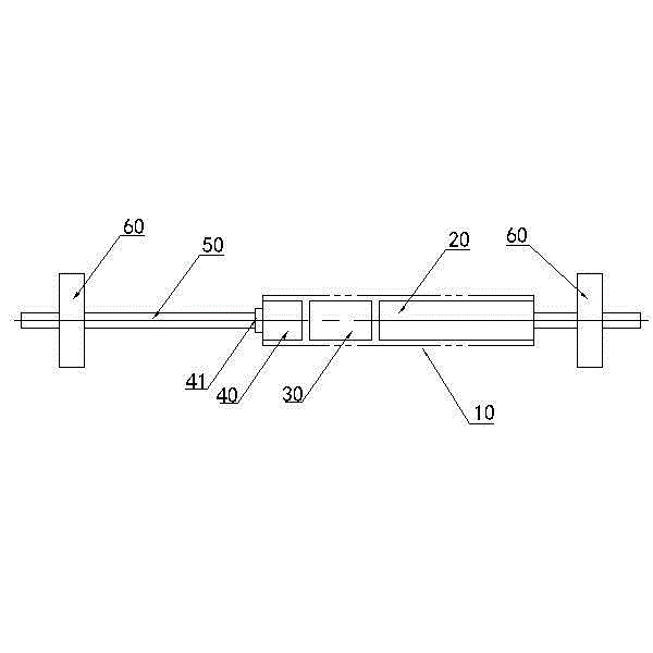
[0015] A special motor for a compact shelf, comprising a motor 20, a speed reducer 30 and a clutch 40, and the motor 20, the speed reducer 30 and the clutch 40 are jointly combined and driven to form an integral structure of a special motor 10 for a tubular compact shelf; the special motor 10 for a tubular compact shelf Among them, the motor 20 is directly connected to the clutch 40 through the planetary gear reduction mechanism of the reducer 30; the output of the clutch 40 is transmitted to the transmission shaft 50, and the drive wheels 60 at both ends of the transmission shaft 50 are realized to drive the compact rack body to move . The motor 20, the speed reducer 30 and the clutch 40 are sequentially arranged and installed in the special motor 10 for the tubular compact rack and connected together through transmission. The motor 20 adopts a deceleration motor to prevent that the driving speed is too fast to cause adverse situations such as moving damage to the compact she...

Embodiment 2

[0017] The motor 20 adopts a 24V DC motor, and the special motor 10 for the tubular compact rack is provided with an AC / DC adjustment control module that converts the 220V AC input into a 24V motor DC power supply. Of course, it is also possible to use a direct 24V external DC power input; the others are the same as in Embodiment 1.

Embodiment 3

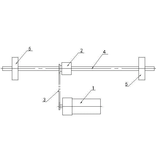
[0019] The special motor 10 for the tubular compact shelf is also provided with one group of spare special motor secondary groups made up of another motor 20 , speed reducer 30 and clutch 40 . When installing and using this moment, on the transmission shaft, a group of transmission gears matched with it can be added to effectively realize the effect of the spare special-purpose motor subgroup driving the transmission compact shelf; other are the same as embodiment 1.

[0020] During use, the output end gear of the special motor 10 for the tubular compact rack of the present invention is on the drive shaft 50, when the compact rack needs to be driven, the output end gear of the special motor 10 for the tubular compact rack is engaged with the drive gear on the drive shaft 50, Realize reliable and efficient driving of the drive wheels of compact racks. When the compact rack is stopped to move, the output gear of the tubular compact rack special motor 10 is separated from the tra...


PUM


Abstract

The invention discloses a compact frame dedicated motor comprising a motor, a speed reducer and a clutch. The motor, the speed reducer and the clutch are combined together in a transmission way so that a tubular compact frame dedicated motor integrated structure is formed. In the tubular compact frame dedicated motor, the motor is directly connected with the clutch via a planetary gear speed reducing mechanism of the speed reducer. Transmission is outputted to a transmission shaft by the clutch so that compact frame driving wheels arranged at the two ends of the transmission shaft are driven, and thus a compact frame body is driven to move. The driving structure is integrally simpler, production installation operation is simpler, convenient and rapid, and production efficiency is high without using transmission of a transmission chain for driving the compact frame by the motor so that an intermediate transmission link of the transmission chain is saved, and space occupied by installation of the whole driving device of the electric compact frame is reduced to a larger extent. Convenient and rapid performance of production installation, disassembling maintenance and repairing operation are enhanced, and fault identification judgment is more accurate, rapid and effective.

Description

technical field [0001] The invention relates to a driving motor used on an electric compact shelf. Background technique [0002] The drive transmission structure of the existing drive motor used on the electric compact rack to the compact rack usually adopts the drive motor 1 and the clutch 2 as separate structures that are independent of each other (see figure 2 ), between the output shaft of the clutch and the output shaft of the deceleration motor through the transmission gear and the transmission chain 3, the output shaft of the clutch is then linked with the transmission shaft 4, and then driven by the transmission shaft to drive The wheels 5 rotate synchronously to work, and then realize the movement of the compact rack. However, such a compact rack motor drive structure has defects such as large space occupation, low transmission efficiency, long drive response time, complex drive structure of the compact rack, high cost, troublesome installation and maintenance oper...

Claims


Application Information

Patent Timeline
Patent Type & Authority Applications(China)
IPC IPC(8): H02K7/116
Inventor 徐益忠汪航舰
Owner 宁波八益智能存储系统有限公司
Why Eureka
Try Eureka