Fuel injection valve

a fuel injection valve and valve body technology, applied in the direction of fuel injection apparatus, movable spraying apparatus, charge feed system, etc., can solve the problems of reducing difficult to make large annular surface area, and not desirable reliability of the above fuel injection valve, so as to improve the efficiency of drive transmission and reduce the effect of charging energy

Inactive Publication Date: 2009-03-12
DENSO CORP
View PDF7 Cites 4 Cited by
  • Summary
  • Abstract
  • Description
  • Claims
  • Application Information

AI Technical Summary

Benefits of technology

[0014]The present invention addresses the above disadvantages. Thus, it is an objective of the present invention to improve drive transmission efficiency while a fuel injection valve is in valve opening operation and to reduce charging energy supplied to a piezo stack. In the above fuel injection valve, a nozzle needle is operated to open a nozzle hole when a piezo stack has a high voltage.

Problems solved by technology

Thus, the above fuel injection valve is not desirable in respect of reliability (e.g., durability) of the piezo stack.
Furthermore, it is difficult to make large an area of the annular surface 941 of the second transfer piston 940.
As a result, problems such as the decrease in the drive transmission efficiency and the deterioration of the spray state become more noticeable.

Method used


Image

  • Fuel injection valve
  • Fuel injection valve
  • Fuel injection valve

Examples


first embodiment

[0029]A first embodiment of the invention is described below.

[0030]A fuel injection valve is attached to a cylinder head of an internal combustion engine (more specifically a diesel engine: not shown), and injects high pressure fuel stored in a pressure accumulator (not shown) into a cylinder of the engine.

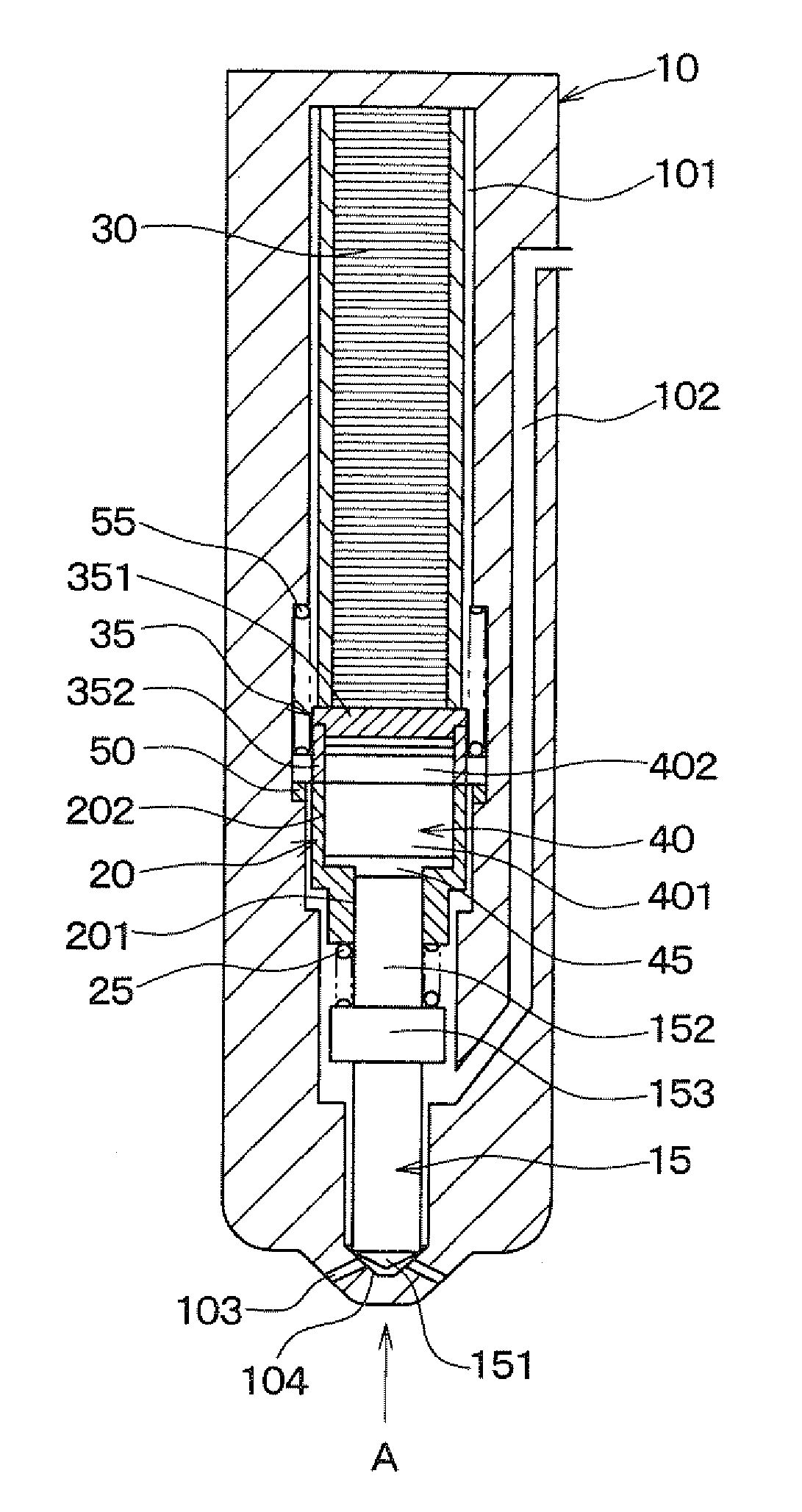
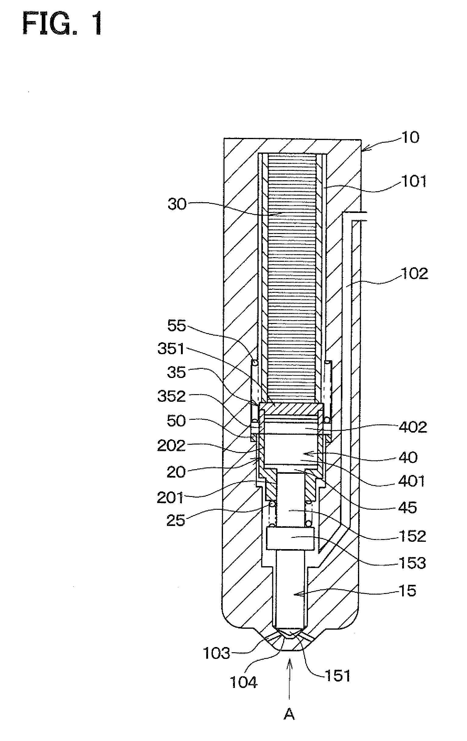
[0031]As shown in FIG. 1, a receiving space 101 having a generally cylindrical shape, a high pressure fuel passage 102, through which high pressure fuel supplied by the pressure accumulator flows, and a nozzle hole 103, through which high pressure fuel is injected into the cylinder of the engine, are formed in a body 10 of the fuel injection valve having a generally cylindrical shape. The receiving space 101 extends along a axial direction (hereinafter referred to as a body axial direction) of the body 10, in a central portion of the body 10 in a radial direction (hereinafter referred to as a body radial direction) of the body 10. The high pressure fuel passage 102 is located outw...

second embodiment

[0052]A second embodiment of the invention is explained below. The same numerals as those used in the first embodiment are used for components, which are the same as or equivalent to the components of the first embodiment, and their descriptions are omitted.

[0053]As shown in FIG. 5, in a fuel injection valve of the second embodiment, a piezo spring 60 is arranged between a body 10 and a cylinder 20. The piezo spring 60 urges the cylinder 20 in a direction in which volume of an oil-tight chamber 45 reduces.

[0054]Accordingly, when the electric charge is discharged from a piezo stack 30 and thereby the piezo voltage falls, the cylinder 20 is returned toward the piezo stack 30 by a nozzle spring 25 and the piezo spring 60. Therefore, a response of the fuel injection valve in closing a nozzle hole 103 is improved.

[0055]Also, because a load of the piezo spring 60 is not applied to a nozzle needle 15, the fuel injection valve has a high degree of flexibility in setting a spring constant of...

third embodiment

[0057]A third embodiment of the invention is explained below. In the third embodiment, a position where a high pressure fuel passage 102 is connected to a receiving space 101 is different from the second embodiment. The same numerals as those used in the second embodiment are used for components, which are the same as or equivalent to the components of the second embodiment, and their descriptions are omitted.

[0058]As shown in FIG. 7, in a fuel injection valve of the third embodiment, the high pressure fuel passage 102 is connected to the receiving space 101 near the other end side of a receiving space 101 in a body axial direction. Accordingly, the high pressure fuel passage 102 does not need to be located near a side surface of the body 10. Thus, reliability (internal-pressure strength) of the fuel injection valve is improved, and a diameter of the receiving space 101 is made large. By making larger the diameter of the receiving space 101, the fuel injection valve has a higher deg...


PUM


Abstract

A fuel injection valve includes a body having a high pressure fuel passage and a nozzle hole, which is connected to the passage, a nozzle needle opening/closing the hole and having a needle piston part, a piezo stack extended when the stack is charged and contracted when the stack discharges electric charge, a cylinder, in which the needle piston part is slidably inserted and which is driven by the stack, a fixed piston having a fixed piston part that is slidably inserted in the cylinder and that has a larger diameter than the needle piston part, an oil-tight chamber between the needle piston part and the fixed piston part in the cylinder, and a nozzle spring urging the needle in a valve closing direction. The cylinder is displaced due to extension/contraction of the stack, so that volume of the chamber increases/decreases and the needle opens/closes the hole.

Description

CROSS REFERENCE TO RELATED APPLICATION[0001]This application is based on and incorporates herein by reference Japanese Patent Application No. 2007-232379 filed on Sep. 7, 2007.BACKGROUND OF THE INVENTION[0002]1. Field of the Invention[0003]The present invention relates to a fuel injection valve for injecting fuel into an internal combustion engine.[0004]2. Description of Related Art[0005]In a fuel injection valve shown in U.S. Pat. No. 6,420,817B1, a valve closing operation is performed on a nozzle needle (i.e., the nozzle needle closes a nozzle hole) when a piezo stack is charged with electric charge to have a high voltage, and a valve opening operation is performed on the nozzle needle when the electric charge is discharged and thereby the piezo stack has a low voltage. In such a case, while an internal combustion engine is in operation, a period during which the piezo stack is at a high voltage is longer than a period during which the piezo stack is at a low voltage. Thus, the ab...

Claims


Application Information

Patent Timeline
Patent Type & Authority Applications(United States)
IPC IPC(8): F02M61/00
CPCF02M51/0603F02M2200/704
Inventor KONDO, JUN
Owner DENSO CORP
Why Eureka
Try Eureka