Supercharge Your Innovation With Domain-Expert AI Agents!

Piston cylinder arrangement of an aerostatic liner compressor

A technology of linear compression and aerostatic bearings, applied in parts of pumping devices for elastic fluids, machines/engines, pump components, etc., can solve problems such as reducing efficiency loss

Inactive Publication Date: 2014-09-10
WHIRPOOL SA
View PDF7 Cites 1 Cited by
  • Summary
  • Abstract
  • Description
  • Claims
  • Application Information

AI Technical Summary

Problems solved by technology

[0026] Therefore, there is currently no linear compressor provided with an aerostatic bearing arrangement that can effectively reduce the loss of efficiency (caused by using cooling gas to provide the bearing arrangement to the piston)

Method used


Image

  • Piston cylinder arrangement of an aerostatic liner compressor
  • Piston cylinder arrangement of an aerostatic liner compressor
  • Piston cylinder arrangement of an aerostatic liner compressor

Examples


Embodiment Construction

[0048] The present invention proposes technical improvements for the piston / cylinder assembly of a linear compressor with an aerostatic bearing arrangement, including improvements in energy efficiency and production process.

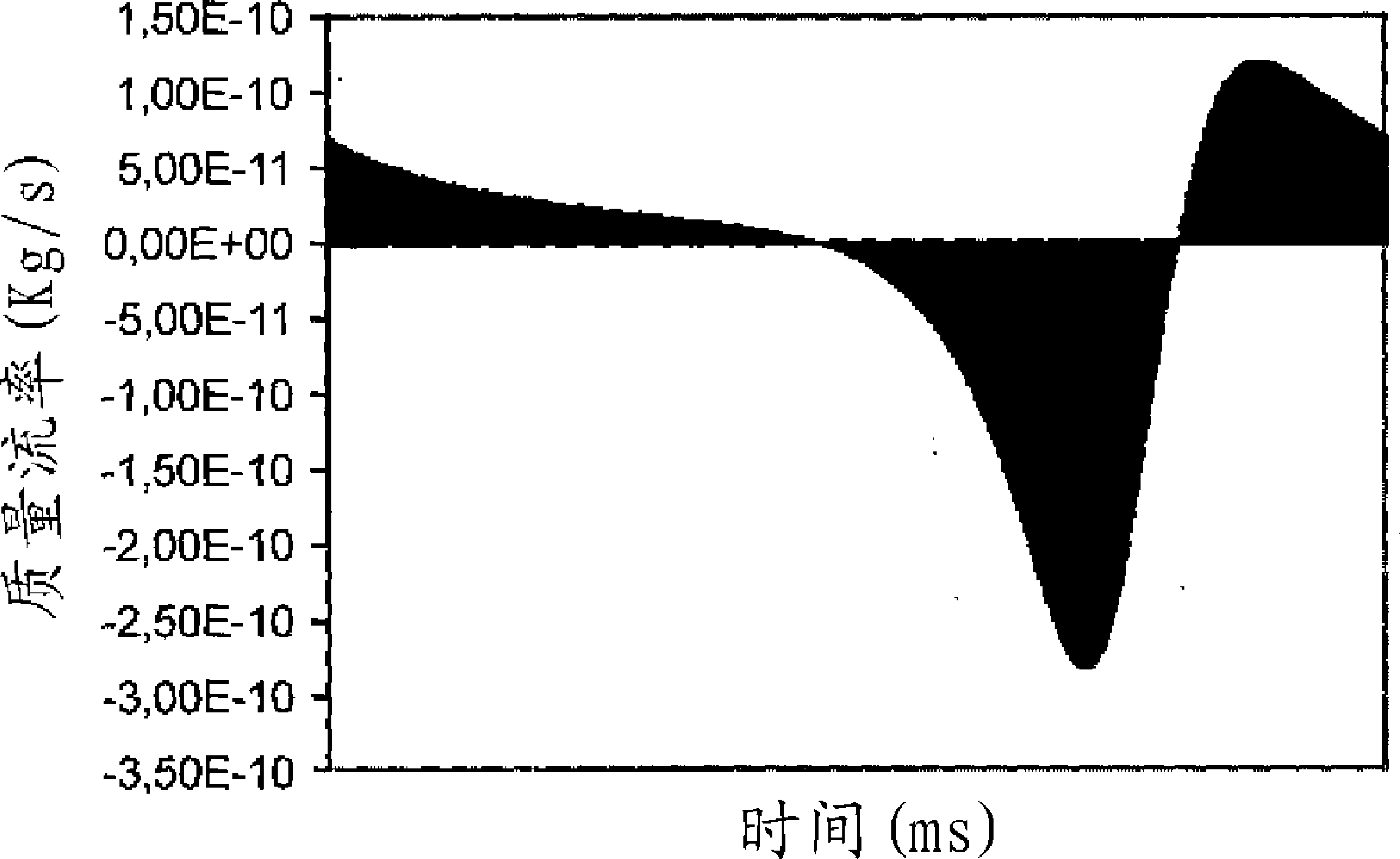
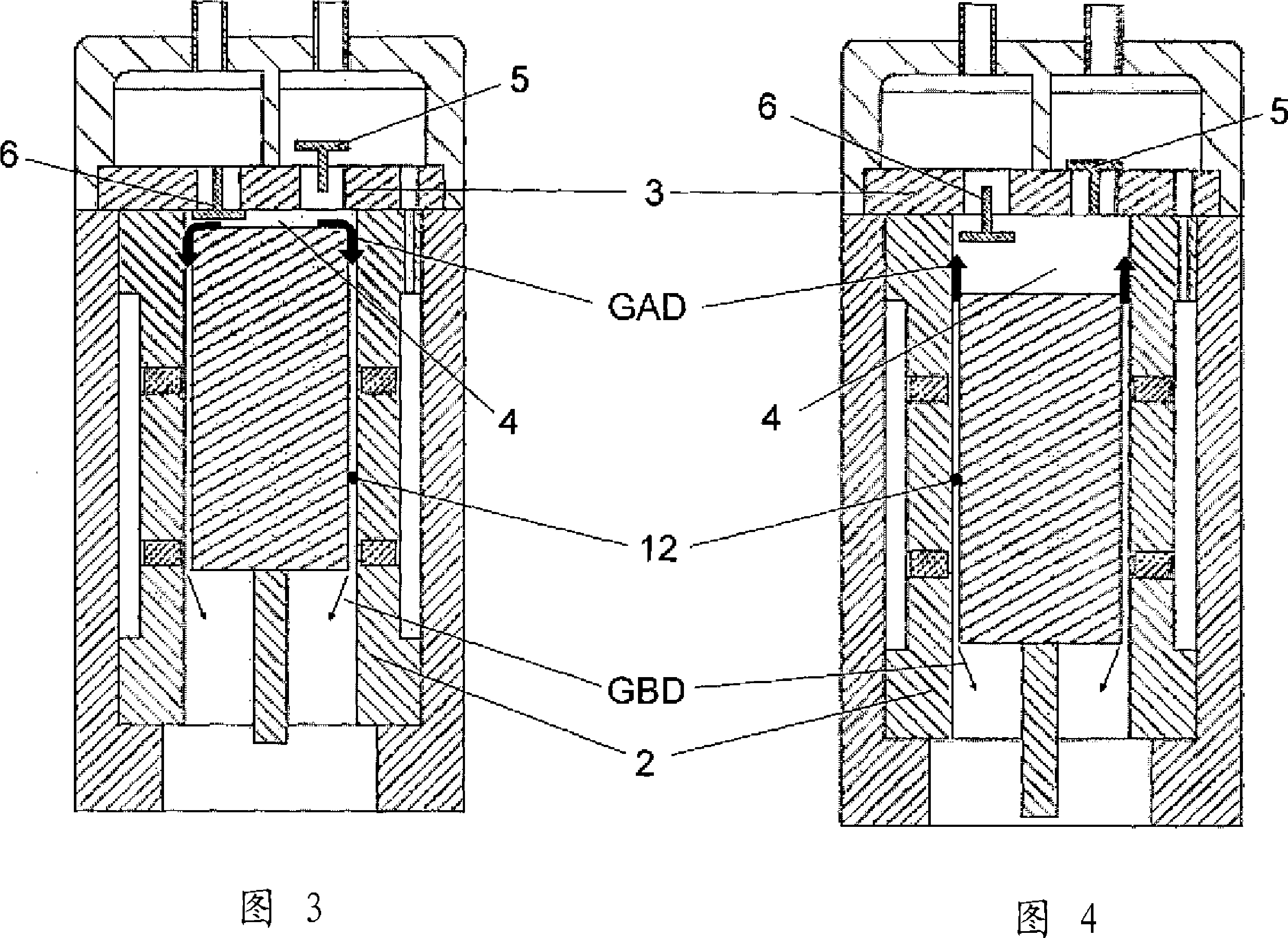
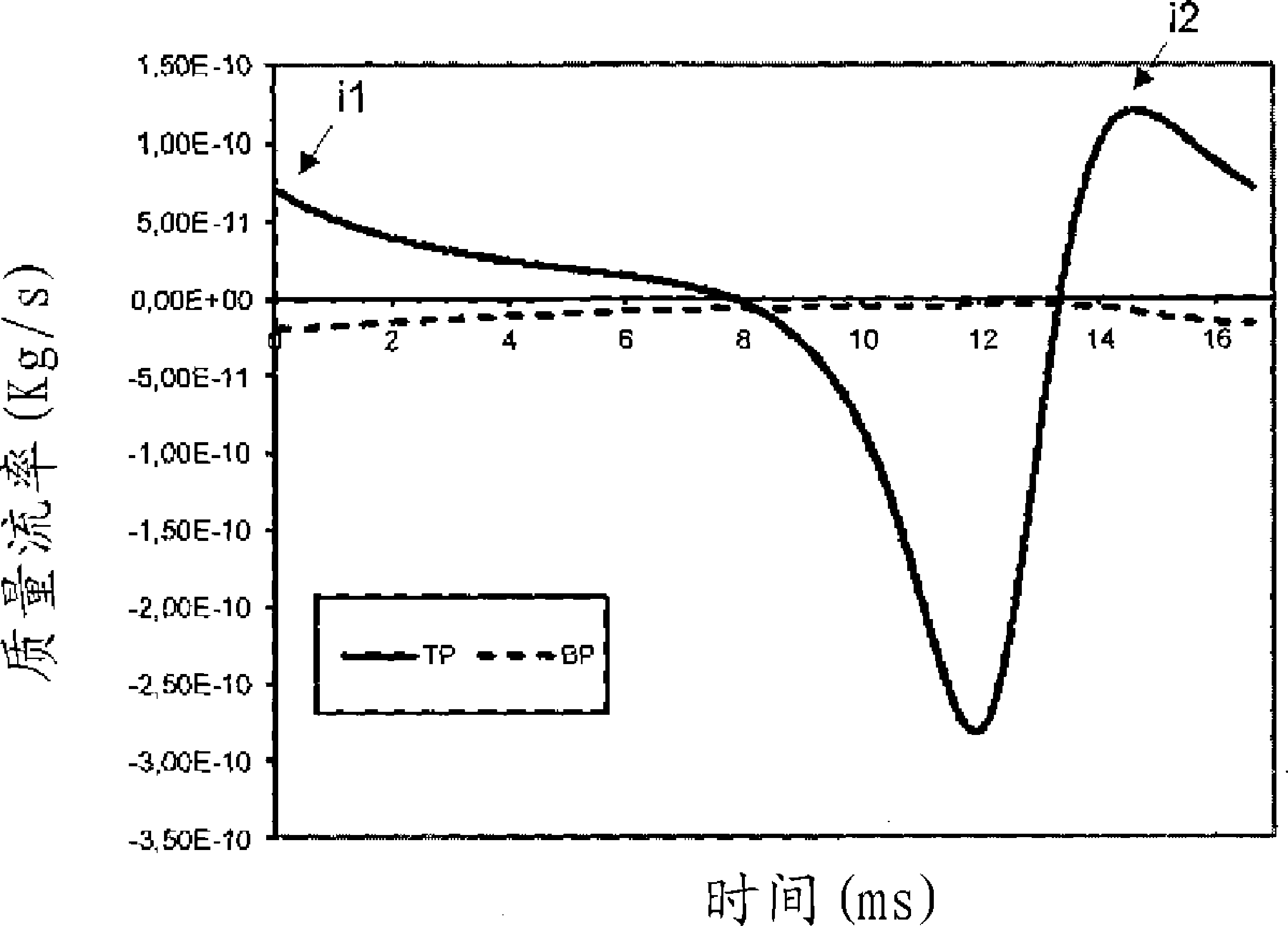
[0049] According to the operating principle of the cooling circuit and as figure 1 As shown, the gas compression mechanism is preferably realized by the axial and oscillatory movement of the piston 1 inside the cylinder 2 . A discharge valve 5 and a suction valve 6 for regulating the entry and exit of gas into and out of the cylinder 2 are arranged at the cylinder head 3 . It should also be noted that the piston 1 is actuated by an actuator 7 connected to a linear compressor motor, which is not the object of further elaboration in this document.

[0050] The piston 1 of the compressor has the function of producing a linear alternating movement when actuated by a linear motor, thereby providing the movement of the piston 1 within the cylinder 2, thereby ...


PUM


Abstract

The present invention relates to a piston (1) and cylinder (2) assembly that can reduce efficiency losses due to the gas in a linear compressor with aerostatic bearings. The space between the piston (1) and cylinder (2) in the piston-cylinder assembly was therefore designed to decrease radial clearance (12) in the upper portion of the piston (1) when the piston approaches the headpiece (3), i.e., when the density of the gas not being used in the refrigeration process is the highest. The piston (1) and cylinder (2) assembly must exhibit such a geometric ratio that radial clearance (12) changes in inverse proportion to the density of the gas in the radial clearance (12).

Description

technical field [0001] The present invention relates to the cooling of a piston / cylinder assembly of a linear compressor having an aerostatic bearing arrangement, and more particularly to the dimensional relationship of the assembly to minimize losses. Background technique [0002] Generally speaking, the basic structure of a cooling circuit includes four components, namely: compressor, condenser, expansion device and evaporator. These elements characterize a cooling circuit in which a fluid circulates in order to be able to lower the temperature of the internal environment, to take heat away from this medium and to transfer it to the external environment through said elements. [0003] Fluid circulating in a cooling circuit typically follows this sequence of passage: compressor, condenser, expansion valve, evaporator, and back to the compressor, which characterizes a closed circuit. During the cycle, the fluid undergoes pressure and temperature changes that cause a change ...

Claims


Application Information

Patent Timeline
Patent Type & Authority Applications(China)
IPC IPC(8): F04B39/02F04B39/12F04B53/00
CPCF04B53/162F04B39/122F04B39/0005F04B39/126
Inventor H.梅勒布雷格曼恩D.E.B.里里伊
Owner WHIRPOOL SA
Features
  • R&D
  • Intellectual Property
  • Life Sciences
  • Materials
  • Tech Scout
  • Unparalleled Data Quality
  • Higher Quality Content
  • 60% Fewer Hallucinations
Learn More