Linear compressor controller

a compressor controller and controller technology, applied in the field of system control, can solve the problems of piston colliding with the head gear, the stroke amplitude is not fixed, etc., and achieve the effect of high power operation

Inactive Publication Date: 2007-05-03
FISHER & PAYKEL APPLIANCES LTD
View PDF10 Cites 32 Cited by
  • Summary
  • Abstract
  • Description
  • Claims
  • Application Information

AI Technical Summary

Benefits of technology

[0007] It is an object of the present invention to provide a control system for a free-piston l

Problems solved by technology

Linear compressors operate on a free piston basis and require close control of stroke amplitude since, unlike conventional rotary compressors employing a crank shaft, stroke amplitude is no

Method used


Image

  • Linear compressor controller
  • Linear compressor controller
  • Linear compressor controller

Examples


Embodiment Construction

[0068] The present invention relates to controlling a free piston reciprocating compressor powered by a linear electric motor. A typical, but not exclusive, application would be in a refrigerator.

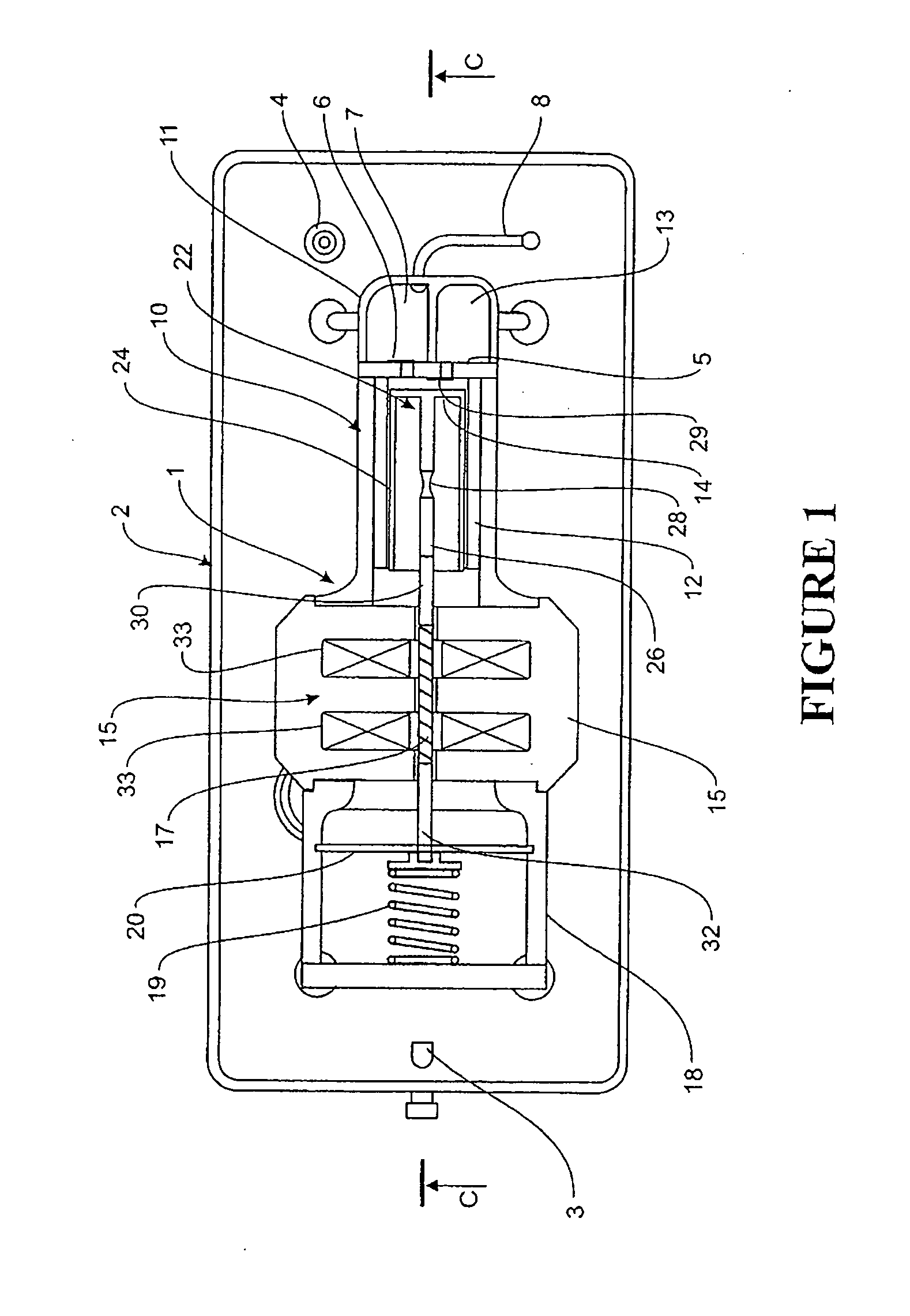
[0069] By way of example only and to provide context a free piston linear compressor which may be controlled in accordance with the present invention is shown in FIG. 1.

[0070] A compressor for a vapour compression refrigeration system includes a linear compressor 1 supported inside a shell 2. Typically the housing 2 is hermetically sealed and includes a gases inlet port 3 and a compressed gases outlet port 4. Uncompressed gases flow within the interior of the housing surrounding the compressor 1. These uncompressed gases are drawn into the compressor during the intake stroke, are compressed between a piston crown 14 and valve plate 5 on the compression stroke and expelled through discharge valve 6 into a compressed gases manifold 7. Compressed gases exit the manifold 7 to the outlet port ...


PUM


Abstract

A free-piston linear compressor (1) controlled to achieve high volumetric efficiency by a controller including an algorithm (116) for ramping up input power until piston-cylinder head collisions are detected using a detection algorithm (117/118) which then decrements power input whereupon input power is again ramped up by algorithm (116). Non-damaging low energy collisions are achieved by the controller including a perturbation algorithm (119) which perturbates the input power ramp with periodic transient pulses of power to ensure piston collisions are provoked during the transient power pulses.

Description

FIELD OF INVENTION [0001] This invention relates to a system of control for a free piston linear compressor and in particular, but not solely, a refrigerator compressor. The control system allow a high power mode of operation in which piston stroke is maximised and collisions deliberately occur. PRIOR ART [0002] Linear compressors operate on a free piston basis and require close control of stroke amplitude since, unlike conventional rotary compressors employing a crank shaft, stroke amplitude is not fixed. The application of excess motor power for the conditions of the fluid being compressed may result in the piston colliding with the head gear of the cylinder in which it reciprocates. [0003] U.S. Pat. No. 6,809,434 discloses a control system for a free piston compressor which limits motor power as a function of a property of the refrigerant entering the compressor. However in linear compressors it is useful to be able to detect an actual piston collision and then to reduce motor po...

Claims


Application Information

Patent Timeline
IPC IPC(8): F25B9/00F25B49/00F02B71/00F04B17/04F04B35/04
CPCF04B35/045F04B2201/0206F25B49/022F25B2400/073F04B49/065F04B49/12F05B2210/12F05B2260/60Y10S417/00
Inventor TIAN, ZHUANGBOYD, JOHN H. JR.
Owner FISHER & PAYKEL APPLIANCES LTD
Why Eureka
Try Eureka