IGCC power station coupling liquefaction air separation equipment system and working method thereof

An air separation plant and power station technology, applied in liquefaction, gasification process, mechanical equipment, etc., can solve the problem that IGCC generator sets cannot respond to grid peak regulation and frequency regulation auxiliary services, and the depth and response rate of peak regulation cannot meet grid requirements and respond. The speed and frequency modulation depth are limited and other problems, so as to increase the output, meet the peak and frequency modulation load requirements, and improve the efficiency.

Pending Publication Date: 2021-07-09
HUANENG CLEAN ENERGY RES INST
View PDF0 Cites 0 Cited by
  • Summary
  • Abstract
  • Description
  • Claims
  • Application Information

AI Technical Summary

Problems solved by technology

[0004] When the IGCC generator set operates under variable load conditions, the system will be limited by the safe and stable operation capabilities of the gasification unit, air separation unit and other equipment, especially the variable load capacity of the existing air separation unit is very limited, resulting in Unable to respond to the requirements of the power grid’s auxiliary services for peak regulation and frequency regulation, the depth and response rate of peak regulation cannot meet the requirements of the power grid, and the response rate and depth of frequency regulation are very limited. sex technology

Method used


Image

  • IGCC power station coupling liquefaction air separation equipment system and working method thereof
  • IGCC power station coupling liquefaction air separation equipment system and working method thereof

Examples


Embodiment Construction

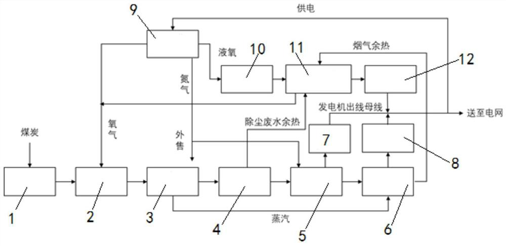
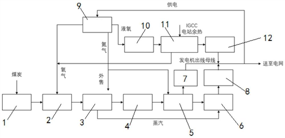
[0037] The present invention will be further described below in conjunction with the accompanying drawings and specific embodiments.

[0038] Such asfigure 1 As shown, the present invention provides an IGCC power station coupled liquefaction air separation equipment system, including a gasifier 2, a waste heat boiler 3, a dust removal and desulfurization purification unit 4, a gas turbine 5 and a waste heat boiler 6 connected in sequence, and coal passes through a coal pretreatment unit 1 Enter the gasification furnace 2 for combustion, after dust removal and desulfurization, connect the gas generator 7 to the gas turbine and the steam generator 8 to the waste heat boiler 6, and the electric energy output of the gas generator 7 and steam generator 8 is connected to the power grid , the power grid also supplies power to the liquefied air separation unit 9, which is a device that adopts a cryogenic liquefaction method to separate air components, and the oxygen outlet of the lique...


PUM


Abstract

The invention discloses an IGCC power station coupling liquefaction air separation equipment system and a working method thereof. The IGCC power station coupling liquefaction air separation equipment system comprises a gasification furnace, a waste heat boiler, a dust removal and desulfurization purification unit, a gas turbine and a residual heat boiler which are sequentially connected, wherein an oxygen inlet of the gasification furnace is connected with a liquefaction air separation device, the liquefaction air separation device supplies energy through a power grid, and a liquid oxygen outlet of the liquefaction air separation device is connected with a liquid oxygen storage tank; an outlet of the liquid oxygen storage tank is connected with a liquid oxygen evaporation expansion unit, the liquid oxygen evaporation expansion unit is used for evaporating liquid oxygen to generate oxygen and expanding to do work, and an oxygen outlet of the liquid oxygen evaporation expansion unit is connected to the oxygen inlet of the gasification furnace. According to the IGCC power station coupling liquefaction air separation equipment system, through the liquid oxygen storage tank and the liquid oxygen evaporation expansion unit, the characteristics of power supply power and load can be quickly and flexibly changed, and the peak regulation and frequency modulation load requirements of the power grid for an IGCC power station are met.

Description

technical field [0001] The invention belongs to the technical field of IGCC power generation, in particular to an IGCC power station coupled liquefaction air separation equipment system and a working method thereof. Background technique [0002] The global climate issue has attracted more and more attention from people, and the "low-carbon economy" characterized by low energy consumption, low emission and low pollution has become a hot spot in the global political and economic game. The power supply in many areas is mainly based on coal power. In order to reduce soot-type pollution, vigorously developing coal-fired technology is an economically feasible research direction to improve coal use efficiency, reduce pollution, and reduce pollution. IGCC power generation technology not only has the high efficiency of combined cycle, but also solves the environmental pollution problem caused by coal-fired power generation. [0003] IGCC is a clean coal power generation technology t...

Claims


Application Information

Patent Timeline
Patent Type & Authority Applications(China)
IPC IPC(8): F01K13/00F01K13/02F01K27/00F01K25/08F01K23/04F01K23/10F25J3/04C10J3/72
CPCC10J3/723C10J2300/093C10J2300/0959F01K13/006F01K13/02F01K23/04F01K23/101F01K25/08F01K27/00F25J3/0403Y02E20/16Y02E20/18Y02P20/129
Inventor 安航杨豫森周贤彭烁
Owner HUANENG CLEAN ENERGY RES INST
Why Eureka
Try Eureka