Linear compressor

a compressor and linear technology, applied in the direction of positive displacement liquid engines, pumps, machines/engines, etc., can solve the problems of high manufacturing cost, complicated manufacturing process, long manufacturing cycle, etc., and achieve the effect of reducing the number of entire main springs, reducing parts production costs, and reducing manufacturing costs of main springs

Active Publication Date: 2011-08-11
LG ELECTRONICS INC
View PDF13 Cites 28 Cited by
  • Summary
  • Abstract
  • Description
  • Claims
  • Application Information

AI Technical Summary

Benefits of technology

[0056]The linear compressor provided in the present invention can reduce parts production costs because the number of the entire main springs is reduced.
[0057]Additionally, the linear compressor provided in the present invention can reduce the manufacturing cost of the main springs because the stiffness of the main springs is reduced.
[0058]Additionally, the linear compressor provided in the present invention can maintain a resonance condition even if the stiffness of the main springs is reduced because the supporter piston is made of metal having a low density and thus the mass of the entire driving unit is reduced.
[0059]Additionally, the linear compressor provided in the present invention can prevent the supporter piston from being abraded by the movement of the front main springs because a region where the supporter piston and the front main springs are contact with each other is surface-treated.
[0060]Additionally, the linear compressor provided in the present invention enables the supporter piston to be easily coupled to the piston because the supporter piston is made of a non iron-based metal and thus has no effect from the permanent magnet.
[0061]Additionally, the linear compressor provided in the present invention can reduce production costs and make control easier because the number of switches at the control unit of the linear motor can be reduced.

Problems solved by technology

Consequently, the manufacturing process becomes complicated and longer and the manufacturing cost is high due to a large quantity of main springs and a large number of parameters to be controlled.

Method used


Image

  • Linear compressor
  • Linear compressor
  • Linear compressor

Examples


Embodiment Construction

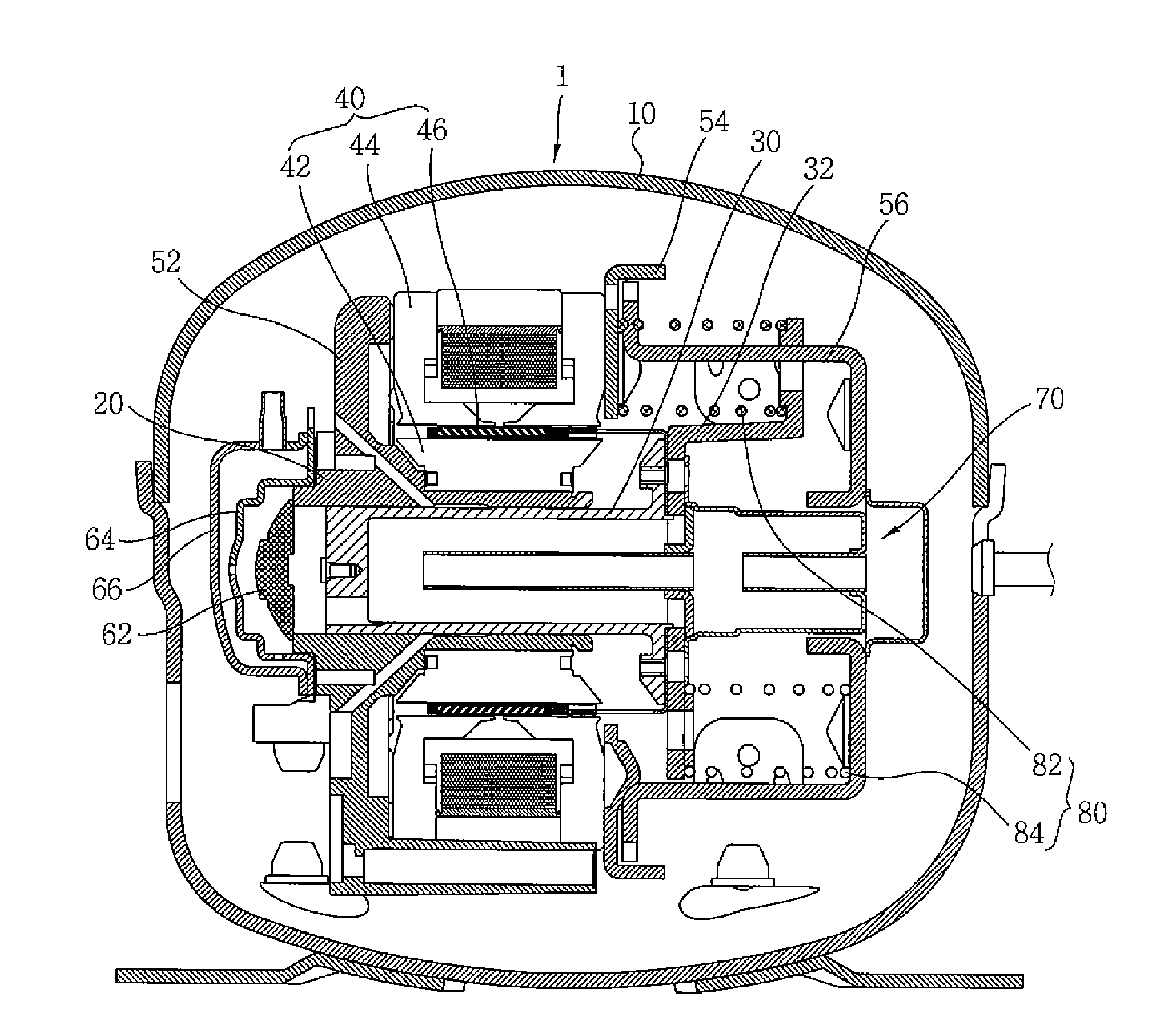
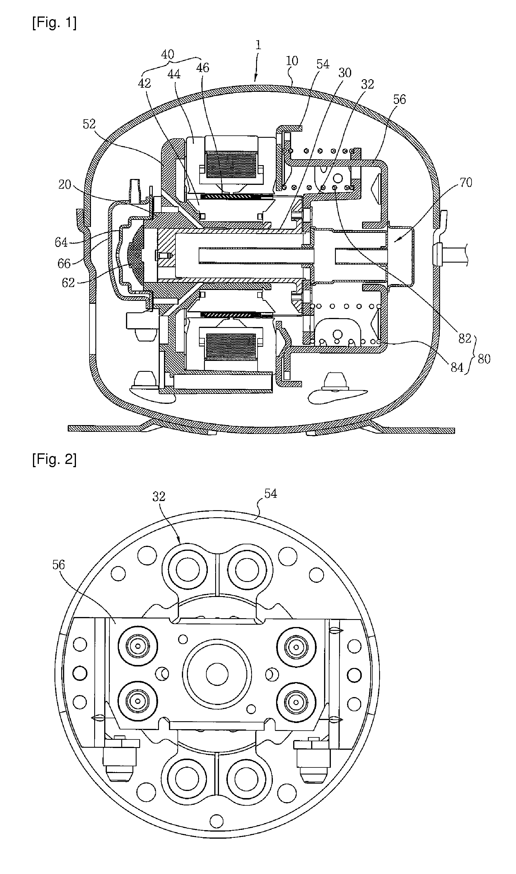
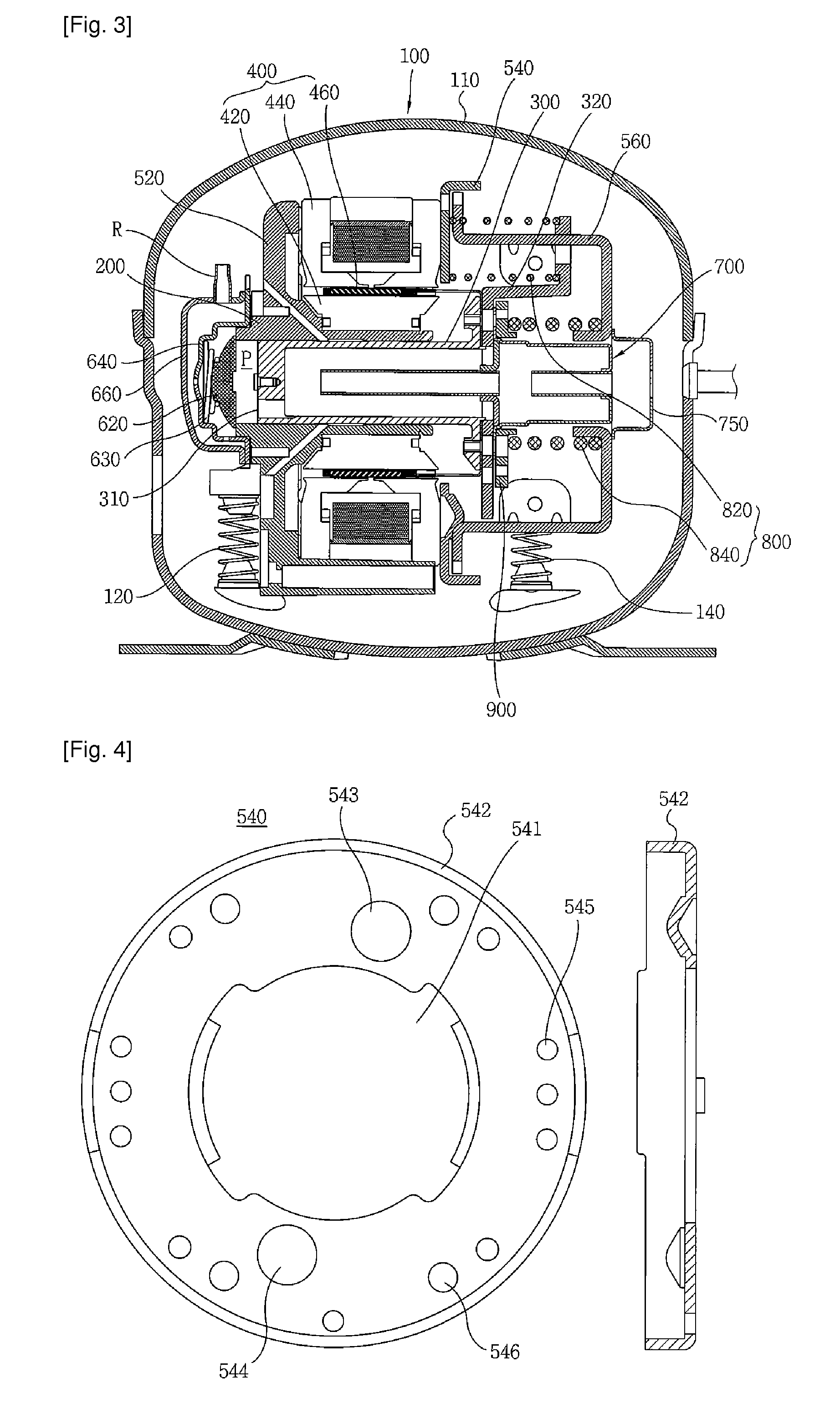
[0106]Hereinafter, the present invention will be described in more detail with reference to the accompanying drawings. FIG. 3 is a view illustrating a cross section of a linear compressor according to one embodiment of the present invention. The linear compressor 110 has parts for compressing a refrigerant within a shell 110, which is a hermetic vessel, the inside of the shell 110 being filled with a low pressure refrigerant. The linear compressor 100 comprises a cylinder 200 providing a space for compressing a refrigerant inside the shell 100, a piston 300 linearly reciprocating inside the cylinder to compress the refrigerant, and a linear motor 400 including a permanent magnet 460, an inner stator 420 and an outer stator 440. When the permanent magnet is linearly reciprocated by a mutual electromagnetic force between the inner stator and the outer stator, the piston 300 connected to the permanent magnet 460 is linearly reciprocated along with the permanent magnet 460. The inner st...


PUM

PropertyMeasurementUnit
massaaaaaaaaaa
strengthaaaaaaaaaa
radiusaaaaaaaaaa

Abstract

There is provided a linear compressor (100), which has a reduced number of front main springs (820) located at the front among springs continuously transmitting a force so that a piston (300) can move in a resonance condition. The linear compressor (100) comprises: a hermetic container (110) to be filled with a refrigerant; a linear motor including an inner stator; an outer stator, and a permanent magnet; a piston linearly reciprocating by the linear motor; a cylinder (200) for providing a space for compressing the refrigerant upon linear reciprocation of the piston (300); a supporter piston (300) having a connecting portion connected to one end of the piston (300) and contacting with the piston (300), a support portion extended from the connecting portion and an additional mass member (350) fixing portion extended from the connecting portion; a plurality of front main springs (820) mounted at positions symmetrical with respect to the center of the piston (300) and the supporter piston (320), one ends of which being supported by one surface of the supporter piston (320); and one rear main spring (840), one end of which being supported by the other surface of the supporter piston (320).

Description

TECHNICAL FIELD [0001]The present invention relates to a linear compressor, and more particularly, to a linear compressor, which makes it easier to manage operating conditions by reducing the number of springs continuously applying a force to a piston so that the piston can perform a resonance operation.BACKGROUND ART [0002]In general, a compressor is a mechanical apparatus for compressing the air, refrigerant or other various operation gases and raising a pressure thereof, by receiving power from a power generation apparatus such as an electric motor or turbine. The compressor has been widely used for an electric home appliance such as a refrigerator and an air conditioner, or in the whole industry.[0003]The compressors are roughly classified into a reciprocating compressor in which a compression space for sucking or discharging an operation gas is formed between a piston and a cylinder, and the piston is linearly reciprocated inside the cylinder, for compressing a refrigerant, a r...

Claims


Application Information

Patent Timeline
Patent Type & Authority Applications(United States)
IPC IPC(8): F04B35/04
CPCF04B35/045B29C45/1671F04B39/0044F04B39/0061F04B39/121F04B49/06F05B2210/12F16B5/02F16F3/04F16F15/04Y10S417/902
Inventor KANG, YANG-JUNJEON, YOUNG-HOAN
Owner LG ELECTRONICS INC
Why Eureka
Try Eureka