Shower head

A technology of sprinkler head and bottom plate, which is applied in the direction of spray device, spray device, indoor sanitary pipe device, etc., can solve the problems of inconvenience and time-consuming of water spray device.

Inactive Publication Date: 2014-09-17
HANSA METALLWERKE AG
View PDF6 Cites 1 Cited by
  • Summary
  • Abstract
  • Description
  • Claims
  • Application Information

AI Technical Summary

Problems solved by technology

[0004] Although this deposit can be removed at intervals by cleaning agents, especially acid-containing cleaning agents, this work is time consuming and cannot be conveniently accomplished with water spraying devices located at the point of use

Method used


Image

  • Shower head
  • Shower head
  • Shower head

Examples


Embodiment Construction

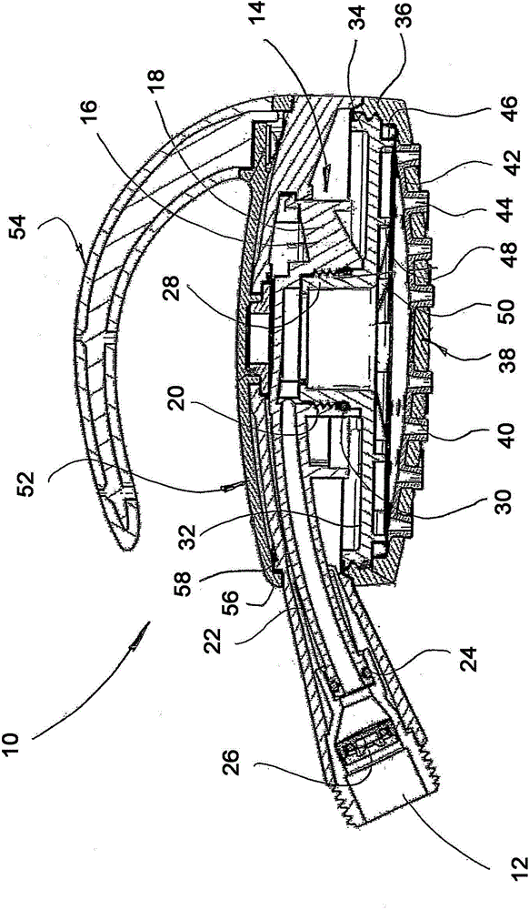
[0035] The hand-held sprinkler shown in the figures has a shower head generally indicated at 10 and a connecting part 12 with a connecting thread for a flexible sanitary hose (not shown).

[0036] Showerhead 10 includes a central base body 14 with a central star bracket 16 . This star-shaped bracket carries via the arm 18 a hub 20 which is equipped with an internal thread. An extended curved supply socket 22 , which carries an O-ring 24 at its free end, exits the spider 16 to the left in the figure. The end section of the supply connection 22 carrying the O-ring 24 engages sealingly in a stepped bore of the connection part 12 , in which a wire mesh 26 is also shown.

[0037] A connecting socket 28 is screwed into the threaded hub 20 , which has a matching thread. The O-ring 30 seals the outer surface of the connection socket 28 against the inner surface of the hub 20 .

[0038] A transverse chamber wall 32 is formed on the lower end of the hub 20 and has an axially retracti...


PUM


Abstract

The shower head has a housing comprising a water inlet (12), a distribution chamber and a beam base (38) provided with a plurality of beam holes (40). The beam base (38) and/or a member (32) holding the chamber base are/is connected with a base body (14) in a detachable manner. Through the above way, the beam base (38) can be cleaned manually or cleaned in a dish-washing machine or a sterilizer mechanically under the condition of being beneficial to ergonomics.

Description

technical field [0001] The invention relates to a shower head / shower head having a housing with a water inlet and a distribution chamber as well as a jet base / water outlet panel (Strahlboden). Background technique [0002] Such shower heads are known as hand-held sprinklers / shower sprinklers or as part of height-adjustable sprinklers on poles or as part of permanently installed sprinklers. [0003] Although only pure water flows through the shower head, over time a deposit consisting mainly of calcium forms on it. It detracts from the appearance. [0004] Although such deposits can be removed at intervals by cleaning agents, especially acid-containing cleaning agents, this work is time consuming and cannot be conveniently accomplished with water spraying devices located at the point of use. Contents of the invention [0005] A shower head which is easy to clean is thus achieved by the invention. [0006] This object is achieved according to the invention in that the jet...

Claims


Application Information

Patent Timeline
Patent Type & Authority Applications(China)
IPC IPC(8): B05B1/18
CPCB05B1/185B05B15/061B05B15/02E03C1/0409B05B15/50B05B15/63B05B15/62
Inventor C·马沙尔
Owner HANSA METALLWERKE AG
Why Eureka
Try Eureka